

ESD safe PU coated work gloves serve as a fundamental safeguard for production line yield and electrical safety in modern high-precision electronic manufacturing, SMT surface-mount assembly, and semiconductor packaging and testing workstations. As chip manufacturing processes continue to scale down to the micrometer and nanometer levels and circuit integration increases exponentially, the tolerance threshold of electrostatic-sensitive devices (ESDS) for transient discharges has been reduced to extremely dangerous levels—within tens of volts or even a few volts.
Introduction: The Hidden Yield Killer in Modern Microelectronics
In highly clean and relatively dry electronic assembly workshops, triboelectric charging is ubiquitous. When front-line operators wear ordinary synthetic fiber gloves to handle materials, move their hands, or perform frequent bending and gripping motions, friction between the glove surface and workpieces or fixtures can instantly build up high-voltage static electricity ranging from 3,000 V to 5,000 V. This static charge—invisible to the naked eye and barely perceptible to the human body—can cause microscopic damage the moment it is discharged upon contact with precision PCBs or chip pins:
Catastrophic Breakdown: Thousands of volts of static electricity discharge transiently through an extremely tiny contact point within nanoseconds. The resulting instantaneous, localized high current density is sufficient to directly melt the micrometer-scale metal interconnects inside the chip or completely break down the insulating gate oxide layer, rendering the chip unusable immediately during factory testing.
Erosion of Product Yield and Reputation Due to Latent Defects: Compared to immediate failure, the “hidden internal damage” caused by low-energy electrostatic discharge is even more destructive. Weak discharges may only cause microscopic lattice damage in the chip’s semiconductor junction region or localized weakening of the insulating layer. While the product may still perform normally during factory electrical testing, it can suddenly fail after several weeks or months of use by end customers due to thermal and electrical stress fatigue, resulting in extremely high recall costs and damage to the company’s brand reputation.
To completely sever the physical chain leading to electrostatic breakdown, high-end anti-static gloves employ an innovative composite material engineering solution—precisely blending highly conductive carbon filaments with continuous polyester/nylon filaments to weave a three-dimensional conductive micro-mesh within the glove, which is then paired with a microporous polyurethane (PU) elastomer coating that features controlled charge migration properties. This architecture precisely controls the surface resistivity within the optimal electrostatic dissipation range of 10^6 to 10^9 ohms (1 megohm to 1,000 megohms, or 1 MΩ to 1 GΩ). It avoids the risk of sparks causing chip breakdown due to instantaneous discharge, as seen with metallic conductors, and prevents the buildup of static electricity, as occurs with ordinary plastics. ensuring that charges are dissipated into the ground in a smooth and controlled manner, while completely eliminating the common drawbacks of ordinary anti-static gloves—such as bulkiness, stiffness, and the tendency to shed lint and particles.
The Physics of Electrostatic Discharge (ESD) in PCB & IC Assembly
During printed circuit board (PCB) assembly, semiconductor wafer dicing, and chip module packaging, electrostatic discharge is not a static physical phenomenon, but rather a transient charge transfer process with extremely high destructive energy. A thorough understanding of the physical damage pathways caused by electrostatic discharge in microscopic semiconductor structures is the theoretical foundation for establishing anti-static protection protocols and selecting consumables for production lines.
Latent Defects vs. Immediate Component Failure
When operators wearing non-anti-static gloves come into contact with integrated circuit (IC) pins, the accumulated static charge is discharged within an extremely narrow pulse duration of just a few nanoseconds (ns), generating transient peak currents as high as several amperes. This energy release at the microscopic level leads to two distinctly different failure modes:
Immediate Failure & Gate Oxide Breakdown: In modern very large-scale integration (VLSI) circuits, the gate oxide layer of metal-oxide-semiconductor field-effect transistors (MOSFETs) is only a few nanometers thick. When a high-voltage electrostatic pulse instantly penetrates the chip’s pin and enters the internal circuitry, the local electric field intensity formed across the oxide layer instantly exceeds the dielectric breakdown voltage, causing irreversible physical breakdown and a short circuit in the insulating layer. At the same time, the localized Joule heating accompanying the discharge instantly melts the micrometer-scale aluminum/copper interconnect lines, resulting in the component being deemed completely defective during the electrical performance testing phase on the production line.
Latent Defects & Field Failure: Low-energy electrostatic discharges at the sub-breakdown level are often insufficient to cause a complete circuit break in the chip, but they leave microscopic melt pits, microcracks, or lattice defects within the semiconductor PN junction or insulating dielectric layer. These “damaged” devices can pass final production line testing and enter the market; however, during long-term operation of the finished product, continuous catalysis from heat generated by operating current and electrical stress fatigue causes the defects to rapidly propagate outward. Ultimately, this leads to sudden system crashes or electrical breakdown during end-user operation, becoming a major hidden hazard that triggers large-scale product recalls and after-sales claims.
Human Body Model (HBM) and Triboelectric Voltage Build-Up
In electrostatic protection engineering assessments, the Human Body Model (HBM) serves as the core standard system for measuring the risk of electrostatic discharge to operators. The human body itself acts as a mobile energy storage device consisting of a capacitor of approximately 100 picofarads (100 pF) in series with a resistor of 1,500 ohms (1,500 ohms):
Peak Triboelectric Voltage Accumulation: In cleanroom environments with relative humidity (RH) below 30%, when frontline workers walk on anti-static flooring, rub their arms against tabletops, or frequently bend their fingers to grasp workpieces, the transfer of electrons between standard insulated gloves and work clothing can easily cause static high voltage ranging from 3,000 V to 5,000 V to accumulate on the human body’s surface.
100-Volt Static Safety Threshold (100V Static Limit Control): According to the ANSI/ESD S20.20 international electrostatic discharge standard, for ultra-sensitive components classified as Class 0 or Class 1 (such as RF chips, thin-film read/write heads, and CMOS image sensors), the residual static voltage on operators’ hands and contact tools must be strictly suppressed to below 100 V; some highly sensitive workstations even require it to be controlled within 30 V. Anti-static gloves must function as a seamless, grounded dissipation path, gently dissipating charges within hundreds of microseconds before the fingertips come into contact with components, thereby preventing high-voltage arc discharges at the source.
Conductive Yarn Engineering: Carbon Monofilament Architecture
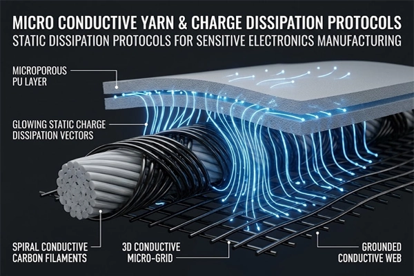
In the material engineering design of anti-static dipped gloves, the conductive architecture of the lining fabric determines the continuity and reliability of the glove’s long-term conductive pathways. Unlike low-end products that rely on surface anti-static sprays (which can quickly lose effectiveness due to friction and washing), professional-grade anti-static gloves must establish permanent conductive pathways at the microscopic textile level.
Carbon Fiber Blending: Creating Microscopic Conductive Grids
To achieve comprehensive electrostatic conductivity while maintaining the fabric’s softness, elasticity, and tactile sensitivity for fine motor tasks, the lining employs a high-grade filament-based conductive composite structure:
Spiral Wrapping Technology for Continuous Filaments and Carbon Fiber Composite Filaments: The lining uses 100% continuous filament polyamide or high-strength polyester as the base carrier fiber, which is precisely woven in a bidirectional spiral wrap with highly conductive carbon black composite filaments. The carbon filaments are not randomly dispersed but are tightly wound around the core of the main yarn at a fixed pitch, ensuring that the conductive path remains closed even when the yarn undergoes tensile deformation.
Three-Dimensional Isotropic Conductive Matrix (3D Isotropic Conductive Matrix): Through a high-density knitting process using a seamless circular knitting machine, the interlaced longitudinal and transverse loops form a three-dimensional mesh of conductive microcircuits on the surface and deep within the glove lining. When static electricity builds up on any part of the operator’s hand, the charge does not need to travel long distances to accumulate; instead, it rapidly and evenly diffuses and dissipates along the nearest microscopic carbon fiber mesh toward the wrist grounding point or the conductive workpad.
Carbon Filament vs. Metal Fiber: Flex Fatigue and Particle Shedding
When selecting conductive materials for anti-static gloves used in microelectronics, carbon fiber composite filaments offer decisive engineering advantages over traditional metal conductive fibers (copper wire, stainless steel microfibers):
Resistance to Repeated Flexural Fatigue and Breakage (Flex Fatigue Resistance): Metal microfibers (such as copper or stainless steel wires with diameters of a few micrometers) have limited toughness and ductility. Under the high-frequency flexing and pinching motions—tens of thousands of times per shift—performed by assembly workers’ fingers, stress concentration at metal grain boundaries can easily lead to plastic fatigue and brittle fracture. Once a metal filament breaks, the local electrostatic conduction path is interrupted, creating an insulating dead zone. In contrast, carbon fiber monofilaments possess an extremely high tensile modulus and molecular elastic recovery; they maintain electrical conductivity even after tens of thousands of bending cycles, with minimal fluctuations in resistance.
Zero Fiber Breakage and Dust-Free Compatibility (Zero Particle Flaking Risk): When metal fibers fracture, their sharp micro-ends can easily pierce the fabric’s surface, causing microscopic metal particles to flake off. If these micron-sized metal particles fall onto chip leads or photoresist surfaces, they can trigger catastrophic short circuits caused by metallic foreign particles. Carbon fiber composite monofilaments are deeply coated with high-molecular-weight polymers, resulting in a smooth, even surface free of loose ends. During long-term friction operations, they achieve zero metal flaking and zero fiber shedding (Zero-Linting), perfectly meeting the particle control standards of high-grade semiconductor and SMT cleanrooms.
Surface Resistivity Dynamics: The Dissipative Golden Range
In anti-static protection engineering, higher electrical conductivity in materials is not necessarily better; both insulation and superconductivity are considered high-risk conditions in microelectronics assembly operations. Precisely regulating the surface resistivity of protective gloves to ensure it remains stable within the static dissipative range is the core physical principle for preventing transient arc discharges and charge accumulation.
The 10^6 to 10^9 Ohm Static Dissipative Threshold
International antistatic standards (ANSI/ESD S20.20 and IEC 61340) provide strict quantitative definitions for the acceptable range of glove surface resistance. Any material deviating from this range poses diametrically opposed yet equally fatal failure risks:
High-voltage charge accumulation traps in insulating materials (Insulative Risk, > 10^11 ohms): When the glove’s surface resistance exceeds 10^11 ohms (as in ordinary latex, PVC, or unmodified synthetic fiber gloves), the glove acts as an electrical insulator. Static charges generated by friction become trapped on the glove’s surface and cannot naturally flow away or dissipate. As the operator performs high-frequency assembly tasks, the static voltage on the hands can rapidly rise to several thousand volts. Upon approaching grounded precision PCBs or metal fixtures, the extremely high potential difference will cause the air medium to break down, resulting in irreversible arc-induced damage.
Electrical sparks and transient high-current surges in low-resistance conductors (Conductive Risk, < 10^4 ohms): When the glove’s resistance is too low (less than 10^4 ohms, approaching that of a metallic conductor), although charge conduction is extremely fast, the discharge process is excessively violent. If a charged workpiece or a person comes into contact with a grounded terminal, the charge will discharge instantaneously within the sub-nanosecond range, producing a transient discharge current with an extremely high peak (Hard Discharge) or even faint sparks visible to the naked eye, which can directly burn through the micrometer-scale aluminum interconnects inside sensitive chips.
The “Static Dissipative Sweet Spot” (10⁶ to 10⁹ ohms): When resistance ranges from 10⁶ to 10⁹ ohms (i.e., 1 megohm to 1,000 megohms), the material provides a continuous, unobstructed conductive path while effectively “limiting and buffering” the discharge current through moderate impedance. This allows accumulated static charges to be released in a controlled and gradual manner to the grounding network within an extremely short timeframe—ranging from 0.1 seconds to several milliseconds—achieving ideal safety protection that prevents the buildup of high-voltage charges while also avoiding the generation of destructive electrical sparks.
Microporous PU Matrix: Enhancing Charge Migration Paths
The microporous polyurethane (PU) elastomer coating on the palm of anti-static gloves not only provides slip resistance and physical fiber locking but also serves as the critical charge conduction interface between the fabric’s conductive backing and the components being handled:
Synergistic Migration Mechanism of the Microporous Honeycomb Network and Conductive Medium: During the wet dipping process, high-quality anti-static PU coatings form a uniform, dense, honeycomb-like microporous structure (Micro-Porous Matrix). Specialized anti-static molecules and long-lasting conductive additives, uniformly dispersed in the formulation, create continuous ion migration channels within the polyurethane elastomer. When the glove surface comes into contact with and is pressed against a chip or fixture, the microporous framework undergoes micro-elastic deformation, causing surface charges to rapidly penetrate the PU coating and be vertically conducted into the densely packed carbon fiber conductive network within the backing.
Balancing long-lasting antistatic stability with low solvent residue: Unlike traditional coatings that rely on hydrophilic small-molecule antistatic agents (which are susceptible to environmental humidity and prone to leaching that contaminates wafers), advanced conductive polyurethane achieves solid-state conductivity through molecular chain modification, resulting in surface resistance that is minimally affected by dry workshop air (e.g., RH < 30%).
For engineering details regarding microporous polyurethane coatings—including the removal of polar solvents, the elimination of volatile organic compound (VOC) emissions, and compliance with the EU’s stringent chemical safety limits—please refer to our in-depth technical guide, Waterborne vs. Solvent-Based PU Gloves: Meeting EU REACH DMFa Limits in Industrial PPE Sourcing, to understand the core standards for solvent-free desalination and cleaning processes.
International ESD Standards & Testing: ANSI/ESD S20.20 & IEC 61340
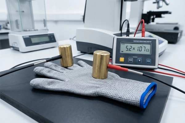
In B2B procurement and EHS (Environment, Health, and Safety) system audits, verifying the technical compliance of anti-static gloves cannot rely solely on verbal assurances from suppliers; it must be based on authoritative international standards and traceable third-party test reports. Currently, the two core ESD standard systems recognized globally in the electronics manufacturing industry are ANSI/ESD S20.20 (North American system) and IEC 61340 (International Electrotechnical Commission/European system).
ANSI/ESD S20.20-2021 and IEC 61340-5-1 Compliance
These two standards provide a unified technical benchmark for establishing, implementing, and maintaining an ESD Control Program. For ESD-safe PU-coated work gloves worn by operators within ESD-protected areas (EPAs), the standards specify strict resistance thresholds:
Core Resistance Requirements: According to the latest edition of ANSI/ESD S20.20-2021, as part of the human grounding system, the system resistance of gloves or finger cots (i.e., the resistance between the wearer’s hand and the ground when the gloves are worn) must be less than 3.5 × 10^7 ohms (35 megohms) before they can be put into service as qualified protective equipment. Meanwhile, the more widely adopted material qualification standard, ANSI/ESD STM15.1, typically requires that the surface resistance or point-to-point resistance of the glove itself fall within the range of 1.0 × 10⁶ to 1.0 × 10⁹ ohms.
EPA Zone Compliance Audits: On assembly lines for extremely sensitive components at the Class 0 (Class 0A/0B) level (HBM with a breakdown voltage below 125 V), EHS auditors strictly verify third-party compliance reports for gloves to ensure that the materials possess long-term, stable electrostatic dissipation capabilities and to prevent insulating materials with triboelectric voltages exceeding 100 V from entering EPA core workstations.
Resistance to Ground (Rg) vs. Point-to-Point Resistance (Rp) Testing
To accurately quantify the electrical performance of anti-static gloves, laboratories typically use the megohmmeter with weighted electrodes method to conduct two core resistance tests, with test procedures strictly governed by the ANSI/ESD STM15.1 or IEC 61340-2-3 standards:
Point-to-Point Resistance (Rp) and Discharge Uniformity: This test evaluates the ability of charge to migrate evenly across the glove’s surface and internal conductive network. During the test, the glove is laid flat on an insulated mat, and two standard conductive rubber electrodes, each weighing 5 pounds (approximately 2.27 kilograms), are placed at different locations on the palm or fingertips of the glove. The Rp test results reflect the uniformity of the glove’s conductive fiber weave, ensuring there are no insulating blind spots on the glove’s surface and preventing localized charge buildup.
Resistance to Groundable Point (Hand-to-Ground, Rg) and System Conductivity: Rg is a key indicator of the glove’s ability to safely dissipate the operator’s static electricity into the grounding system. The most accurate Rg test is conducted with the operator actually wearing the gloves, holding a heavy hammer electrode in one hand and touching an antistatic mat or the ground terminal of the resistance tester directly with the other hand. This test evaluates whether the complete electrical path—from the operator’s skin, through the glove lining, the carbon fiber conductive mesh, and the wrist cuff, all the way to the grounding point—is unobstructed.
Key Effects of Test Voltage (10 V vs. 100 V) and Relative Humidity (RH 12% vs. 50%):
Test Voltage Calibration: For ESD-safe PU-coated work gloves, when the material resistance is expected to exceed 10⁶ ohms, the standard requires testing with a 100 V DC voltage (±5%) to obtain stable readings. Some non-professional reports use 10 V to test high-resistance dissipative materials; the results are often lower than expected and fail to accurately reflect the material’s charge dissipation behavior when subjected to friction voltages of several thousand volts in actual production.
Ambient Humidity Calibration: Resistance test results are highly dependent on ambient humidity. According to E-E-A-T (professional) requirements, a valid test report must specify the temperature and humidity conditions during pretreatment and testing. Anti-static gloves typically undergo the most rigorous “low-humidity environmental simulation pretreatment” (such as 48–72 hours of pretreatment in a drying oven at 12% RH ± 3%) and are tested under these low-humidity conditions. Only gloves that still meet the 10^6 to 10^9 ohm range under low-humidity conditions can ensure electrostatic safety in northern winters or in air-conditioned production lines year-round. Qualifying data obtained under high-humidity conditions, such as 50% RH, are of no reference value for dry workshop environments.
ESD Glove Benchmark Matrix: Carbon PU vs. Nitrile vs. Cotton
When evaluating materials for microelectronics manufacturing and SMT production lines, procurement teams and electrostatic discharge (ESD) engineers often weigh the options between knitted conductive-coated gloves, disposable film gloves, and traditional all-cotton anti-static gloves. There are significant differences among these substrate materials in terms of electrostatic dissipation rate, surface resistance stability, particulate shedding control, and total cost of ownership (TCO) per workstation per shift.
Comprehensive Electrical, Particulate, and Cost-per-Shift Data
To provide quantifiable engineering data for product selection in precision electronics assembly and cleanroom environments, the table below provides a side-by-side comparison of carbon-blended anti-static PU gloves (Carbon-Blended PU), cleanroom anti-static nitrile gloves (Cleanroom ESD Nitrile), anti-static PVC gloves (Anti-Static Vinyl), and anti-static cotton gloves (ESD Cotton) in terms of core electrical performance, particulate emission, and ergonomics:
| Evaluation Metrics | Carbon-Blended PU Gloves (Carbon-Blended PU) | Cleanroom ESD Nitrile Gloves | Anti-Static PVC Gloves (Anti-Static Vinyl) | Anti-static 100% Cotton Gloves (ESD Cotton) |
| Surface Resistivity | 10^6 to 10^9 ohms (permanent electrostatic dissipation range) | 10^9 to 10^11 ohms (depending on formulation modifications or surface treatment) | Greater than 10^11 ohms (high insulation; high voltage builds up easily due to friction) | 10^7 to 10^10 ohms (highly dependent on workshop humidity) |
| Static Decay Time (5,000 V to 50 V) | Less than 0.1 seconds (rapid and smooth charge dissipation) | 0.5 to 2.0 seconds (slow dissipation) | Cannot dissipate effectively (charges remain trapped for extended periods) | 0.8 to 3.0 seconds (dissipation performance declines sharply in dry environments) |
| Particle Loss Control (LPC, diameter ≥ 0.5 micrometers) | Extremely low (continuous filament lining combined with PU-locked fibers, less than 1,200 particles/cm²) | Extremely low (seamless cast film; cleanroom-grade with fewer than 800 particles per square centimeter) | Moderate to high (plasticizer particles leach out, exceeding 3,000 particles per square centimeter) | Extremely high (woven from short fibers; dust emission exceeds 10,000 particles per square centimeter; produces significant lint) |
| Fingertip Tactile Feedback | Extremely high (13-gauge/18-gauge ultra-thin bonded lining, enabling precise handling of tiny components) | Moderate to high (depending on film thickness, 3 to 5 mil) | Low (the film is relatively stiff, causing significant resistance to finger movement) | Extremely low (thick, bulky fabric; lacks fine tactile sensitivity when pinching with fingers) |
| Breathability and Moisture-Wicking (Breathability) | Excellent (exposed knit mesh on the back of the hand keeps hands dry and sweat-free all day) | Zero breathability (fully sealed film; hands become saturated with sweat during prolonged wear) | Zero breathability (stuffy and sticky, prone to causing skin allergies and redness) | Good (natural fibers absorb moisture and allow breathability, but repeated friction can cause heat buildup and deformation) |
| Total Cost Per Shift per Workstation (Cost-Per-Shift) | Extremely low (high mechanical abrasion resistance, suitable for continuous wear for 1 to 3 shifts, low total cost of ownership) | High (disposable; prone to punctures from sharp pins; each person uses multiple pairs daily) | Moderate (low unit price but highly prone to tearing, resulting in high overall wastage) | Relatively high (frequent shedding requires frequent replacement and washing, resulting in high hidden maintenance costs) |
In actual workstations such as SMT surface mounting, precision PCB assembly, and chip visual inspection, carbon fiber anti-static PU gloves have become the preferred solution for preventing electrostatic damage and reducing the overall procurement costs of consumables, thanks to their consistent static dissipation capabilities, excellent breathability and moisture-wicking performance, and exceptional fingertip dexterity.
For further information on the systematic differences between polyurethane (PU), nitrile rubber (Nitrile), and natural latex (Latex) in terms of underlying polymer film-forming mechanisms, oil resistance ratings, and mechanical abrasion resistance testing, please refer to our technical selection guide, PU Coated vs. Nitrile vs. Latex Work Gloves: The Definitive B2B Selection Guide for Precision Manufacturing, for comprehensive materials engineering data.
Grip Ergonomics & Coating Configurations: Fingertip vs. Palm-Coated
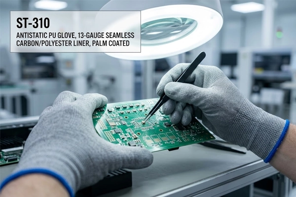
In precision microelectronics assembly and semiconductor testing workstations, anti-static gloves serve not only as a safe discharge path for static charges but also as an extension of the operator’s tactile senses. The knit density of the liner and the coverage area of the polyurethane coating directly determine frontline workers’ operational efficiency, fatigue resistance, and the yield rate for handling microscopic components.
13-Gauge Precision Liner for Fine Component Handling
In SMT surface mount assembly, wafer probe station calibration, and precision micromechanical assembly, the 13-gauge conductive liner strikes a balance between structural rigidity and tactile sensitivity:
High-precision gripping of tiny surface-mount components and anti-slip feedback: When operators use anti-static tweezers or micro-vacuum pens to pick up 0201 (0.6 x 0.3 mm) or even 01005 (0.4 x 0.2 mm) ultra-micro passive components, gloves that are too bulky or lack elasticity can easily cause micro-tremors in the hands, resulting in components being knocked out of place or leads being bent. The 13-needle high-density weave uses high-resilience polyester/nylon and carbon fiber composite filaments that closely conform to the contours of the palm and knuckles, providing micro-pressure feedback that feels almost like bare hands when the fingers pinch.
Force perception for inserting and removing micro-flexible printed circuit (FPC) cables: During the assembly of smartphone camera modules and automotive central control motherboards, handling micro-FPC cables (ZIF/BTB connectors) requires precise perception of the faint snap-in resistance of approximately 0.5 newtons. The 13-pin lining eliminates the numbness and sluggishness associated with traditional, bulky gloves, allowing assembly workers to clearly discern whether a connector is fully seated, thereby completely eliminating cold solder joints and poor connector contact.
For an in-depth engineering analysis of how knit density (gauge) affects microscopic fabric thickness, finger flexion resistance, and the optimization of cycle time (CT) per unit, please read our technical guide: 13-Gauge vs. 18-Gauge PU-Coated Gloves: Maximizing Tactile Sensitivity in Micro-Assembly Lines.
Fingertip (Top-Fit) vs. Palm-Coated Grounding Paths
Given varying workstation cleanliness requirements and operating conditions, selecting the appropriate coating—whether fingertip (Top-Fit) or full-palm (Palm-Fit)—is a key strategy for optimizing ergonomics and electrostatic conductivity:
Passive Heat Dissipation and Agility in Fine Motor Control with Finger-Immersion Coating (Top-Fit / ST-300): The finger-immersion design applies a polyurethane elastomer coating only to the fingertips and pads of the five fingers, while the entire palm and back of the hand remain exposed, featuring a conductive carbon fiber knit mesh. In electronic assembly workshops with constant ambient temperatures, the exposed fabric areas provide excellent channels for air convection, allowing sweat from the palms to evaporate quickly and preventing the hands from remaining in a stuffy, damp state for extended periods. At the same time, the microporous PU coating on the fingertips ensures the grip required for fine motor tasks, making it ideal for high-frequency, light-duty workstations such as visual inspections on SMT production lines, light-load component sorting, and circuit debugging.
Full-Palm Coating (Palm-Coated / ST-310) for Large-Area Conductivity and Particle-Trapping Barrier: The full-palm coating process completely covers the entire palm and the front surfaces of all five fingers with a polyurethane coating, creating a continuous physical barrier and a large-area conductive contact surface. When handling large-size PCBs, modules with metal shielding, or coming into contact with large grounding fixtures, the full-palm coating provides a larger effective contact area, allowing static charges from the body to be discharged to the grounding mat via a shorter path and at a more uniform density. In addition, the full-palm PU coating completely seals the fabric fibers of the palm, effectively preventing the penetration of skin flakes and salt from sweat, resulting in superior anti-fouling performance in cleanrooms with extremely stringent particle control requirements.
For a systematic analysis of the microscopic fiber-locking mechanism of polyurethane coatings and high-grade cleanroom particle release control standards, please refer to our cleanroom technical white paper, Lint-Free PU Cleanroom Gloves: Preventing Particulate Contamination in Semiconductor Environments.
Wash Durability & Conductive Longevity
In the management of consumable costs at large EMS contract manufacturers and microelectronics manufacturing companies, whether anti-static gloves are capable of withstanding repeated washing and reuse is a key indicator for evaluating their total cost of ownership (TCO) and cost-effectiveness. However, the wash life of anti-static fabrics cannot be determined solely by the degree of visible damage; the key lies in whether the microscopic conductive network inside the gloves can maintain stable electrostatic dissipation performance after washing cycles.
Static Decay Stability Over Multi-Cycle Cleanroom Laundering
Conventional gloves that rely on surface antistatic agent coatings have their surfactants completely stripped away after just 1 to 2 washes, causing surface resistance to rapidly degrade to a high-risk insulating state exceeding 10^11 ohms. In contrast, high-quality ESD-safe PU-coated work gloves woven from carbon fiber composite filaments exhibit a markedly different performance decay curve when subjected to standardized cleanroom laundering:
Stability of Surface Resistance and Electrostatic Decay Time: When processed on a professional clean-washing line using 18 megohm deionized water (DI water) and a nonionic neutral surfactant, carbon fiber blended gloves—during the first 3 to 5 wash cycles—maintain a stable surface resistance within the benchmark range of 10⁶ to 10⁸ ohms as trace impurity ions remaining from the weaving and dipping processes are removed. and the electrostatic decay time (from 5,000 V to 50 V) consistently remains at an extremely high level of less than 0.1 seconds.
Decay inflection point after multiple washes: As the number of wash cycles increases beyond 8, continuous water flushing and mechanical friction cause the polyurethane microporous coating to exhibit microscopic fatigue swelling, and the surface carbon fiber wrapping layer undergoes slight wear. At this point, the point-to-point resistance (Rp) slowly rises to 10⁸ to 10⁹ ohms, but remains within the safe electrostatic dissipation range permitted by the ANSI/ESD S20.20 standard. If the number of washes exceeds 10, the glove’s electrostatic decay time begins to lengthen significantly; it is recommended that the gloves be reassigned from Class 0 core workstations.
Standard Operating Procedures to Prevent Conductive Filament Fracture
To maximize the service life of anti-static gloves and prevent physical breaks in the carbon fiber conductive network, companies must establish standardized cleaning and drying procedures (SOPs):
Control of Washing Machine Shear Forces and Spin Speed: Although carbon fiber monofilaments possess extremely high tensile strength, they are sensitive to severe torsional and shear stresses. Industrial dust-free washing machines should use a gentle wash cycle with low speed (recommended main wash speed of 30 to 35 rpm) and a low water level; the use of high-speed centrifugal spin-drying equipment is strictly prohibited. Excessive centrifugal shear forces can easily cause microscopic fatigue fractures in the carbon fiber monofilaments at the interlacing points of the fabric loops, resulting in localized open circuits in the conductive network.
Requirements for Washing Media and Water Purity: Deionized water or softened water with extremely low conductivity must be used. Detergents containing hypochlorites, strong acids, strong alkalis, or cationic surfactants are strictly prohibited. Strongly oxidizing detergents accelerate the hydrolytic aging of the polyurethane coating and disrupt the electrical continuity of the carbon black composite layer.
Temperature Limits for Low-Temperature Positive-Pressure Drying: After dehydration, gloves must be placed in a clean dryer equipped with a HEPA/ULPA high-efficiency air filtration system. The drying temperature must be strictly limited to 60 degrees Celsius (60°C) or below, and the drying time must be controlled within 30 to 45 minutes. Excessively high drying temperatures can cause thermal-oxidative aging and embrittlement of the polyurethane elastomer, and may subject the carbon fibers in the glove’s inner layer to destructive tensile stress during the cooling and contraction process. After drying is complete, random resistance testing must be performed on an antistatic workbench, followed by double-layer antistatic vacuum sealing and packaging.
Strategic Sourcing: SQG® Antistatic (ESD) Precision Lineup
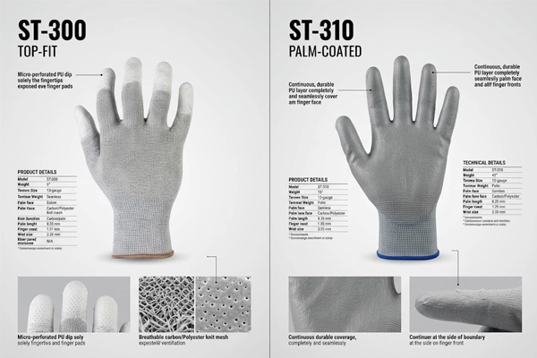
As a source manufacturer, SQG® has developed a proprietary line of antistatic laminated products based on conductive carbon fiber composite weaving technology to meet the demanding antistatic and micro-handling requirements of modern microelectronics manufacturing. Through differentiated engineering adjustments to the weave count of the backing fabric, the ratio of conductive yarns, and the polyurethane coating profile, SQG® provides direct-sourcing solutions for SMT production lines, semiconductor packaging and testing, and consumer electronics assembly that combine reliable electrical protection with operational comfort.
SMT Fine Inspection Standard: ST-300 (13-Gauge Carbon Top-Fit)
For lightweight precision-handling workstations requiring ultimate tactile feedback and high breathability, the ST-300—a 13-gauge seamless carbon/polyester liner with finger-coated tips—is the model of choice for production line engineering supervisors and procurement managers:
Fingertip Micro-Perforated Polyurethane Dip-Coating Technology (Top-Fit Coating): The ST-300 applies a micro-perforated PU coating only to the fingertips and pad areas of all five fingers, while the palm and back of the hand retain the original knitted mesh of highly conductive carbon fiber interwoven with highly elastic polyester. This structure provides operators with fingertip grip sensitivity nearly equivalent to that of bare hands. When handling 0201/01005 surface-mount resistors and capacitors, micro crystal oscillators, camera motor modules, and optical prisms, it completely eliminates mechanical damage to components caused by finger slippage or excessive force.
Superior Heat Dissipation, Breathability, and Long-Lasting Anti-Static Protection: The exposed knitted structure on the palm allows sweat to evaporate instantly through convection, completely eliminating the discomfort of sweat buildup and stuffiness found in traditional fully enclosed gloves. At the same time, the carbon fiber conductive mesh distributed throughout the glove lining ensures that static charges generated by fingertip contact are gently dissipated along the mesh at the moment of contact. The surface resistance is consistently maintained within the range of 10^6 to 10^8 ohms, making these gloves ideal for SMT AOI final visual inspection, chip visual inspection, and light-load manual component placement stations.
Full-Surface Dissipative Benchmark: ST-310 (13-Gauge Carbon Palm-Coated)
For continuous assembly operations requiring large-area contact dissipation, full-palm slip-resistant grip, and high mechanical abrasion resistance, the ST-310—a 13-gauge seamless carbon/polyester liner with a palm coating —sets the engineering benchmark for industrial-grade electrostatic protection:
Full-Palm Coating for Extensive Electrostatic Discharge Path (Full-Surface Dissipative Path): The ST-310 features a microporous polyurethane coating that completely covers the entire palm and the front surfaces of all five fingers, creating a continuous conductive contact interface and a physical protective layer. When handling large, multi-layer PCBs, automotive electronic control modules with metal shielding, or operating grounded conductive fixtures, the full-palm coating provides a larger effective contact area, allowing static charges from the body to be safely dissipated to the grounding mat via an extremely short path and at a low current density, thereby preventing localized point discharges and breakdown.
Physical fiber-locking dust protection and high abrasion resistance: The continuous, dense polyurethane coating completely seals the fabric fibers in the palm’s load-bearing areas, effectively preventing the shedding of skin flakes and the leaching of sweat ions; particle release is far lower than that of ordinary knitted gloves. In addition, the full-palm PU coating offers excellent abrasion and tear resistance, capable of withstanding prolonged friction and scraping from sharp PCB edge traces, significantly extending the service life of single and double gloves and reducing the total cost of consumables per shift per workstation in the factory.
For a comprehensive overview of SQG®’s full range of polyurethane work gloves—including those for general high-precision assembly, eco-friendly water-based dipping, ultra-clean dust-free environments, and anti-static applications—as well as specifications and factory-direct bulk purchasing solutions, please visit our core product catalog, Precision PU Palm-Coated Work Gloves Direct from Manufacturer, to access detailed product manuals and technical support for bulk purchases.
Quality Assurance: Auditing ESD Test Reports & Line Acceptance
In supplier qualification audits for electronic manufacturing services (EMS) and semiconductor packaging and testing facilities, quality assurance (QA/QC) for anti-static gloves must be based on rigorous quantitative data and standardized sampling procedures. Procurement teams and EHS engineers must not only verify the technical accuracy of third-party laboratory reports but also conduct standardized on-site acceptance tests before materials are put into inventory and used on the production line.
How to Verify Third-Party ESD Test Certificates
When reviewing third-party test reports provided by suppliers, corporate auditors should focus on verifying the following four core technical parameters to prevent non-compliant or “data-manipulated” consumables from entering the Electrostatic Protected Area (EPA):
Pre-conditioning and Test Environment Temperature and Humidity Calibration (Pre-Conditioning RH% Check): This is the primary indicator for determining the validity of a report. The conductivity of anti-static polymers is highly susceptible to moisture in the air. Compliant reports must explicitly state that the samples underwent pre-conditioning under constant temperature and humidity conditions for no less than 48 to 72 hours in a low-humidity environment (relative humidity RH 12% ± 3%, temperature 23°C ± 2°C). Any pass results obtained solely at 50% RH or under standard temperature and humidity conditions cannot demonstrate the glove’s antistatic effectiveness during dry northern winters or in temperature-controlled, dehumidified cleanrooms.
Test Voltage Settings and Standards Version: Verify that the testing is based on the currently valid ANSI/ESD STM15.1 or IEC 61340 series standards. For electrostatic dissipative materials with a surface resistance of 10^6 ohms or higher, the testing equipment must automatically or manually switch to a 100V DC test voltage. If a testing organization improperly uses a low-voltage 10V test on high-resistance materials, the measured resistance values are often artificially low and fail to reflect actual electrostatic discharge conditions.
Test Electrode Specifications and Applied Pressure (Electrode Pressure & Weight): Standard testing must use a standard conductive rubber weighted hammer electrode with a diameter of 63.5 mm (2.5 inches), a weight of 5 pounds (2.27 kg ± 5%), and a Shore A hardness of 50–70. Any test report that uses a handheld touch probe or does not specify the electrode pressure is not valid for engineering compliance purposes.
Daily Factory Acceptance Testing (FAT) Using Surface Resistance Meters
To ensure batch consistency in bulk shipments, the factory’s quality management department should establish clear standard operating procedures (SOPs) for incoming material sampling and daily production line inspections:
Incoming Quality Control (IQC) Sampling Protocol: In accordance with AQL sampling standards, randomly select samples from each incoming batch and place them on the production line’s standard anti-static test bench to perform actual measurements of point-to-point resistance (Rp) and resistance between the test object and ground (Rg).
On-site Operating Procedures for the Heavy-Hammer Surface Resistance Tester:
Step 1 (Calibration and Zeroing): Turn on the metrologically calibrated high-resistance meter/megohmmeter and use a standard resistance calibration block to verify the instrument’s measurement accuracy within the 10³ to 10¹² ohm range.
Step 2 (Point-to-Point Test Rp): Place the sample glove flat on an insulating mat with a surface resistance greater than 10¹³ ohms. Place the two 5-pound hammer electrodes on the palm and fingertip areas of the glove, respectively (maintaining a distance of 25 to 50 millimeters between the electrodes). Select the 100V test setting, apply power, and maintain the test for 15 seconds. Read the stable resistance value. The pass/fail range must fall between 1.0 × 10⁶ and 1.0 × 10⁹ ohms.
Step 3 (Hand-to-Ground System Resistance Test, Rg): The inspector must actually wear the sample gloves, grip the cylindrical handheld electrode firmly with one hand, or press the palm flat against the 5-pound hammer electrode, while the other end of the tester is connected to the workshop’s dedicated ESD grounding bar (ESD Ground). Measure the total resistance from the skin through the glove lining to the ground terminal; the acceptance criterion is a system resistance of less than 3.5 × 10⁷ ohms.
Step 4 (Recording and Batch Traceability): If the resistance of a sampled glove exceeds the specified range or if the resistance value fluctuates by more than one order of magnitude, immediately isolate the batch of materials for further inspection and initiate the supplier’s traceability process for the consistency of conductive fiber blends.
Knowledge Base: Frequently Asked Questions (FAQs) & CTA
In the context of microelectronics electrostatic discharge (ESD) control systems and PPE procurement practices, various technical questions often arise regarding material properties, resistance classifications, and workstation compatibility. The following summarizes the key questions and engineering answers most relevant to production line engineers and procurement teams:
Can standard white PU gloves cause ESD damage to IC components?
Yes, standard white general-purpose PU gloves pose an extremely high risk of electrostatic discharge at sensitive electronic workstations. Standard white PU gloves typically feature a standard polyester/nylon liner and an unmodified polyurethane coating; their surface resistance is usually greater than 10^11 ohms, classifying them as electrical insulators. In a dry workshop environment, the rapid hand movements of operators can easily generate static electricity through friction, causing thousands of volts of static charge to accumulate on the glove surface. When approaching or contacting sensitive IC pins, the static charge on the insulating layer can cause uncontrolled transient discharges, directly breaking down the gate oxide layer or causing potential lattice damage. Therefore, within ANSI/ESD S20.20 protected areas, the use of ordinary insulating gloves that do not contain blended conductive fibers for direct contact with electrostatic-sensitive devices (ESDS) is strictly prohibited.
What is the difference between antistatic, static dissipative, and conductive gloves?
The key differences among the three lie in the range of surface resistivity of the materials and the control of charge dissipation rates:
Conductive gloves (resistance less than 10^4 ohms): Charge moves extremely quickly, but upon contact with a charged object, they are prone to instantaneous high-current discharges (hard discharge), which can generate sparks that burn out micro-semiconductor circuits. They are generally used in explosion-proof environments or at special grounding workstations.
Static-dissipative gloves (resistance between 10⁶ and 10⁹ ohms): These are the gold standard in microelectronics manufacturing. They dissipate charge into the ground at a gradual, controlled rate (typically less than 0.1 seconds), preventing both charge buildup and transient high-current breakdown.
Antistatic/Insulation-Suppression Type (Antistatic, resistance 10⁹ to 10¹¹ ohms): These gloves primarily suppress static voltage generated by friction (typically less than 100 V), but their charge dissipation rate is relatively slow, making them suitable for general assembly areas with lower sensitivity requirements.
How does relative humidity (RH%) affect the ESD performance of carbon fiber gloves?
Carbon fiber filament-blend gloves are extremely independent of workshop air humidity and maintain consistent electrical conductivity under all conditions. Low-end gloves that rely on surface antistatic agent coatings must absorb water molecules from the air to form a conductive film; once the workshop relative humidity (RH) drops below 30%, their surface resistance skyrockets to insulating levels, causing them to fail completely. In contrast, the carbon fiber composite filaments used by SQG transmit charges through solid-state conductive pathways (a microscopic conductive grid of carbon atoms). Even during the extremely cold and dry winters in northern regions or in ultra-clean, dehumidified workshops where humidity is strictly controlled between 12% and 20%, they can consistently maintain a dissipation range of 10^6 to 10^8 ohms, ensuring uninterrupted protection.
When should an electronics production line choose the ST-300 (top-fit) over the ST-310 (palm-coated)?
The choice between the two depends on the type of workstation operations and specific requirements for breathability and comprehensive barrier protection:
Choose ST-300 (Top-Fit): Suitable for workstations requiring extremely high fingertip pinch sensitivity, high-frequency fine motor control, and extended wear. Examples include micro-picking of SMT components, AOI visual inspection, optical lens focusing, and chip testing stations. The exposed knitted mesh on the palm provides excellent convective cooling and prevents hand perspiration.
Choose the ST-310 (Palm-Coated): Suitable for work environments requiring large-area ESD discharge contact, strong anti-slip grip, and a highly abrasion-resistant barrier. Examples include the handling and assembly of large-size PCB motherboards, assembly of complete device enclosures, insertion of components with metal shielding covers, and strict workstations that require prevention of skin flakes or sweat ions from penetrating the palm.
H3: Call to Action (CTA)
Establish a robust electrostatic safety barrier for your SMT production lines and microelectronics assembly workshops to eliminate potential chip breakdown and yield loss at the source.
Looking for authoritative EPA-level test reports, technical specifications, and bulk purchase samples for your production lines? Feel free to contact our engineering support team at Request ESD Test Reports & Free Sample Kits to receive a customized solution.
To explore our complete lineup of polyurethane industrial gloves—including ultra-thin, high-sensitivity, eco-friendly water-based, and dust-free cleanroom options—please visit Explore ESD-Safe & Cleanroom PU Gloves Lineup. Connect directly with our manufacturing facilities to optimize the total cost of ownership (TCO) for your consumables procurement.


