Introduction
In multinational supply chain vendor audits of global precision electronics manufacturing, semiconductor packaging, and automotive Tier-1 production lines, the quality consistency of ESD-protective gloves is facing an unprecedented crisis of confidence. Many procurement auditors frequently encounter the “uncontrolled impedance trap” when taking on-site samples: for gloves from the same incoming batch, the surface resistance variation can span four orders of magnitude—ranging from 10^5 ohms, which poses a risk of hard discharge, to over 10^9 ohms, which provides complete insulation. An even more insidious industry practice is that a large number of low-cost small workshops rely heavily on applying moisture-absorbing surfactants to the exterior of the gloves; Such products can pass initial factory inspections in testing environments with humidity exceeding 50% RH, but when used in dry workshop airflow or after 90 days of warehouse storage, the surface water film and coating rapidly fail, completely degrading into high-static insulators—directly causing catastrophic latent arc damage to high-speed surface-mount technology (SMT) machines and high-precision circuit boards.
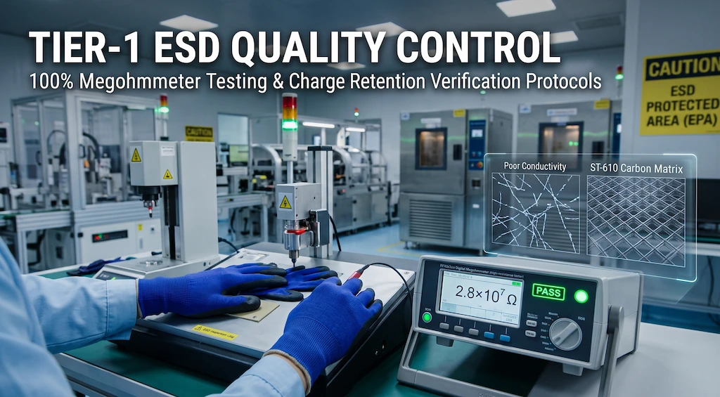
To break this batch-quality paradox—where products “pass factory inspections but fail in production”—it is essential for the actual manufacturing facilities to establish a fully digitalized, end-to-end ESD glove manufacturing surface resistance QC access control system. True automotive-grade manufacturing does not rely on pre-shipment sampling and labeling, but rather begins with initial screening—including the melting of conductive masterbatch and four-probe resistance testing of carbon fiber filaments—and continues through mandatory testing in a pre-conditioning chamber maintained at a constant temperature and humidity of 25% RH for extreme drying, followed by 100% megohmmeter testing of boxed products using concentric electrode pressure. This process seals every quality loophole with tamper-proof, physically measured data. When establishing an end-to-end electrostatic safety firewall for ultra-large-scale precision production lines, the process team must match the appropriate protection matrix based on cleanroom class and assembly stress. For in-depth information on the full range of automotive-grade configurations covering different weave densities, palm-and-finger dipping processes, and surface impedance gradients, please refer to the overview of the ESD Safe & Antistatic Gloves main category, which includes a complete range of microelectronics protective equipment.
The Vendor Audit Crisis: Unmasking Inconsistencies in Batch Resistance
During on-site vendor quality audits at multinational electronic manufacturing services (EMS) and automotive electronics giants, the variability in the anti-static performance of incoming materials is often the first crack to shatter the illusion of low-cost supply chain management. Traditional work glove manufacturing systems lack an engineering understanding of semiconductor-grade charge dissipation characteristics. In workshop-style factories without strict closed-loop control, gloves are simply viewed as mechanically sewn assemblies consisting of “woven fabric and dipped rubber.” When auditors use calibrated high-resistance meters to conduct consecutive spot checks within the same batch of packaging boxes, they often find that the resistance data exhibits a random, scattered distribution; this severe electrical non-uniformity within a batch constitutes the systemic root cause of sporadic board failures and unexplained component damage across different shifts on automated SMT production lines.
The Four-Orders-of-Magnitude Impedance Trap
On production lines without quality control checks, the measured point-to-point resistance (Rp-p) of gloves from the same batch and with the same box number often fluctuates wildly between 1.0×10^5 ohms and 1.0×10^9 ohms, spanning a full four orders of magnitude:
Impedance avalanche caused by uneven dispersion of conductive media: In small workshops, when preparing dipping solutions, workers typically manually add ingredients into open mechanical mixing tanks. Conductive carbon black particles or antistatic additives are highly prone to agglomeration or localized settling in water-based or solvent-based polyurethane emulsions. When concentration gradients within the coating tank become uncontrolled, the surface coating of gloves dipped in the early stages of the production line becomes enriched with excessive conductive particles, causing the resistance to drop abruptly to below 1.0 × 10⁵ ohms; such low-impedance coatings, which fall within the conductive range, can trigger nanosecond-level “hard discharge” micro-sparks upon contact with charged semiconductor pins, directly causing gate breakdown in the chip under the Charged Device Model (CDM);
Conductive dead zones induced by unstable knitting tension: On simple knitting machines without constant tension control, the interlacing spacing between conductive fibers (such as bicomponent carbon fiber filaments) and the polyester base filaments is extremely unstable. When changes in bobbin damping cause a sudden increase in yarn feed tension, the fine conductive carbon filaments may suffer microscopic breaks or failures in the warp-weft interlacing; This results in large-area mesh breaks (conductive dead zones) in localized areas of the finished gloves, causing the measured point-to-point resistance to instantly surge to over 1.0×10⁹ ohms;
Catastrophic static buildup caused by high-resistance insulation: Once the local resistance of the glove exceeds 1.0×10⁹ ohms, the material degrades into a high-resistance insulating state. When workers are rapidly assembling PCBA boards, the static charge generated by friction cannot be smoothly dissipated into the grounding system within milliseconds. As a result, the static potential at the fingertips can build up to several thousand volts within seconds, rendering the wrist straps and anti-static grounding networks—which were originally installed—completely ineffective.
Surfactant Wash-Off vs. Permanent Conductive Matrix
To cut corners without increasing the costs of precision carbon fiber weaving and high-purity polyurethane, low-end supply chains commonly adopt processes involving the external spraying or dipping of hygroscopic surfactants (such as quaternary ammonium compounds):
The “shelf-life cheating” mechanism of moisture-absorbing coatings: Surfactants such as quaternary ammonium salts are polar molecules. Their antistatic mechanism does not rely on the free electronic transitions within the material, but rather depends entirely on hydrophilic groups forcibly adsorbing moisture from the surrounding air. This forms an extremely thin, microscopic water film on the glove’s outer surface, enabling weak electrical conductivity through the migration of hydrated ions. During factory acceptance testing or initial unboxing tests, if the workshop is in a high-humidity environment (such as during summer or on production lines where humidity is not strictly controlled), the water film on the glove surface is sufficient, and an impedance meter will often register seemingly合格 readings of 10^7 to 10^8 ohms;
The “three-to-six-month natural degradation” trap: These surfactant molecules are physically attached to the surfaces of the fabric and rubber layers solely through weak van der Waals forces and do not form chemical bonds with the polymer substrate. When exposed to high temperatures during shipping container transport, stored in a warehouse for more than 90 days, or subjected to airflow in the workshop, the surfactant molecules will spontaneously volatilize, crystallize, or oxidize and degrade. When dry winter air enters the workshop, the partial pressure of water vapor in the air drops sharply, causing the outer water film to dry up completely. As a result, the surface resistivity of the gloves surges directly into the pure insulation range of over 1.0×10¹⁰ ohms;
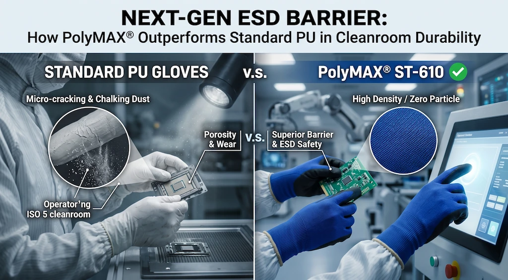
The truth is laid bare by dust-free cleaning: In semiconductor and high-grade cleanroom production lines, gloves often require rinsing with ultrapure deionized water (DI water) before use to remove ionic contaminants. Under deionized water rinsing, the surface-applied surfactants are completely washed away within tens of seconds, causing the rinsed gloves to lose all conductivity. In contrast, the high-density, physically interwoven carbon fiber filament network used in state-of-the-art superfactories features a conductive network deeply embedded within the polymer fiber core. Possessing intrinsic physical properties such as water insolubility, abrasion resistance, and oxidation resistance, its conductive dissipation pathways remain permanently stable regardless of the number of dust-free wash cycles or extreme drying conditions endured.
Raw Material Gatekeeping: In-Line Conductive Filament Metrology
In the initial manufacturing stages of the semiconductor and automotive electronics supply chains, the fundamental line of defense that determines the yield rate for quality inspection is not at the end of the dip coating line, but at the weighing and resistance measurement stations during incoming quality control (IQC). The charge-neutralizing performance of automotive-grade anti-static gloves is fundamentally determined by the microscopic lattice structure and carrier mobility of the conductive filaments within the fabric matrix. If the conductive yarn delivered by raw material suppliers exhibits fluctuations in intrinsic line resistance or microscopic broken-fiber defects, no subsequent advanced molding process can correct the localized resistance drift in the finished gloves. Therefore, superfactories must establish an extremely rigorous electrical calibration and access control system for the conductive yarn of every batch and every spool before the circular knitting machines are started.

Four-Probe Resistivity Screening on Yarn Spools
For spools of bicomponent conductive carbon fiber filaments and ultra-fine alloy conductive copper wires entering the workshop’s material preparation area, the quality control team must eliminate traditional visual inspections or rough multimeter spot checks and fully implement a standardized Incoming Quality Control (IQC) Standard Operating Procedure (SOP) based on the four-probe testing principle:
The four-probe mechanism eliminates contact resistance errors: Conventional two-probe measurements are highly prone to introducing parasitic contact resistance of hundreds or even thousands of ohms due to uneven contact between the probe metal and the rough surface of the conductive fibers, resulting in severely distorted measurement results. The high-precision four-probe micro-resistance tester installed at the factory applies a constant, highly stable milliamperes (mA) DC test current via the two outer probes, while the two inner probes use high input impedance to measure the absolute potential difference across the sample. This physical measurement principle eliminates interference from contact resistance and the internal resistance of external wires;
Continuous Dynamic Yarn Resistance Measurement and Tolerance Band Locking: Quality inspectors select cones from each batch of incoming raw yarn according to a stricter sampling ratio, mount them on a constant-speed pay-off tension frame, and allow the yarn to pass uniformly through the four-probe electrode fixture, performing continuous in-line measurement of the yarn resistance per meter. For bicomponent conductive carbon yarns used in high-density knitting, the nominal linear resistance must strictly converge within a standard baseline of several thousand ohms per meter, and the tolerance for resistance fluctuations per unit length is strictly limited to an extremely narrow threshold window of ±5%;
Interception of non-conforming bobbin batches and removal of fused knots: As soon as the system detects a sudden surge in impedance in a section of yarn due to uneven dispersion of carbon black masterbatch, or a thinning of the conductive core layer caused by a clogged spinneret, the four-probe measurement and control instrument will immediately trigger an audible and visual alarm and automatically cut and mark the affected section; Any spool of yarn where the entire batch deviates beyond the ±5% tolerance will be marked and returned to the original manufacturer, thereby strictly preventing defective raw material batches from entering subsequent knitting operations.
Continuous Filament Purity to Prevent Dead-Zone Knitting
In addition to electrical impedance consistency, the microscopic mechanical morphology of conductive fibers also plays a decisive role in eliminating localized antistatic failures:
The blending of short fibers is strictly prohibited; a continuous filament baseline must be established: Many low-cost contract manufacturers, in an effort to reduce yarn procurement costs, blend cut and fragmented carbon fiber short fibers with cotton or polyester roving. At the microscopic level, these short fibers are separated from one another and rely on random, haphazard interlocking to form conductive pathways. During glove wear and stretching, as well as repeated bending of the finger joints, the microscopic contact points between short fibers are extremely prone to being pulled apart, creating grid breaks invisible to the naked eye. This causes the contact area on the fingertips to instantly degrade into an insulating “conductive dead zone” incapable of discharging static electricity;
Closed-loop warp and weft tension control on 13-gauge and 18-gauge fully automatic circular knitting machines: The SQG production line strictly uses full-length, seamless continuous filaments and bicomponent carbon fibers for warp and weft knitting:
In the weaving of 13-gauge medium-thickness inner liners for circuit board assemblies, conductive carbon filaments are interwoven in both the warp and weft directions at a microscopic, uniform spacing of approximately 5 mm;
In the weaving of 18-gauge ultra-high-density, precision micro-assembly inner liners, finer-denier continuous nylon filaments are used to encase the conductive carbon core, significantly increasing the stitch density;
Online yarn breakage monitoring via microscopic low-force tension sensors: Each yarn feed channel on every automated knitting machine is equipped with a piezoelectric microscopic low-force tension sensor to monitor knitting tension fluctuations in the range of tens of millinewtons (mN) in real time. As soon as a single fine fiber of the conductive carbon yarn breaks or becomes knotted and skips a stitch, the sensor detects the sudden drop in tension within 5 milliseconds and triggers an emergency shutdown of the knitting machine. This physical closed-loop monitoring, implemented during the knitting stage, ensures that the three-dimensional topological grid of conductive warp and weft threads—across the palm, fingertips, and even the angles between the fingers—is uniform and leaves no dead zones, providing the finished gloves with uniform, symmetrical, and isotropic charge transfer capabilities.
Environmental Pre-Conditioning: The 25% RH Anti-Cheating Protocol
In the field of metrological testing for anti-static equipment, environmental humidity is the most critical external variable determining the results of insulation resistance and surface resistance measurements. Many low-end suppliers often exploit the “water film effect” in electrostatic physics to mask the materials’ inherent electrical defects, allowing gloves that would otherwise fail to pass routine testing. To restore the product’s true protective performance in extremely dry industrial environments and eliminate misjudgments of batch quality caused by temperature and humidity manipulation, reputable state-of-the-art manufacturing facilities must implement anti-cheating low-humidity environmental pre-conditioning access protocols in accordance with stringent international standards.
24-Hour Conditioning Chamber Protocol (EN 16350 / IEC 61340)
A common flaw in routine industry testing is that testers conduct resistance tests directly in uncontrolled, open workshops or in high-humidity environments with relative humidity (RH) as high as 50% to 60%:
False pass results caused by the polarization of water molecules in high-humidity environments: When the relative humidity of the air exceeds 50% RH, even pure polyester or standard polyurethane gloves containing absolutely no conductive fibers will spontaneously adsorb water vapor molecules from the air onto their polymer surfaces, condensing into a continuous film of adsorbed water only a few nanometers thick. Under the influence of a weak electric field, water molecules become oriented and polarized; combined with trace ions released from the dissociation of carbon dioxide dissolved in the air, this forms a temporary aqueous ionic conduction pathway on the glove’s outer surface. When measured with a megohmmeter at this point, the instrument will display a value of 10^7 to 10^8 ohms, which appears to be compliant; however, this conductivity is entirely an illusion caused by the water film. Once the gloves are brought into a dry winter workshop or a high-airflow cleanroom, the surface resistivity will immediately rebound to a dangerous insulation range of over 10^10 ohms;
Minimum Humidity Control Baseline per European EN 16350 and IEC 61340 Standards: SQG Super Factory eliminates all possibilities of moisture-related fraud at the source by strictly enforcing the rigorous humidity control pretreatment procedures specified in the European anti-static glove standard EN 16350 and the International Electrotechnical Commission (IEC) standard IEC 61340:
Precision environmental chamber parameter calibration: Test samples are placed inside a high-precision constant-temperature and constant-humidity test chamber, where the temperature is locked at 23 degrees Celsius (with a tolerance of ±1 degree), and the relative humidity is precisely maintained at 25% RH (with a tolerance of ±3%);
24-Hour Deep Dehydration and Drying: Test samples are continuously suspended and exposed under extreme dry conditions at 25% RH for at least 24 hours. This deep dehydration process forcibly removes all non-bound free water molecules and physically adsorbed water films from the microporous structure of the polymer fibers, eliminating external aqueous conductive pathways;
Forcing the material to reveal its intrinsic conductive network: Under extreme conditions where environmental moisture assistance is completely lost, externally sprayed surfactant-based pseudo-anti-static products are exposed for what they truly are, with impedance instantly exceeding the standard by tens of thousands of times; In contrast, automotive-grade products such as ST-610 and ST-310, featuring a homogeneous, co-woven, two-component carbon fiber three-dimensional continuous topological network, rely on the quantum tunneling and transition of free electrons in their pure physical state through the gaps between carbon particles to transfer charge; their measured vertical resistance (Rv) remains firmly within the standard range of less than 1.0×10⁸ ohms, demonstrating true all-season stability against environmental drift.
In-Situ Testing Without Disrupting the Chamber Atmosphere
After completing 24 hours of extreme low-humidity preconditioning, isolating the physical environment during testing serves as the second technical safeguard against data distortion:
The physical risk of rapid secondary moisture absorption triggered by removing samples from the chamber: A common operational error in standard laboratories is removing preconditioned samples from the test chamber and laying them flat on a standard workshop inspection bench for measurement. The moment they leave the 25% RH chamber, the extremely dry polymer fibers and microporous polyurethane coating exhibit a strong capillary effect for moisture absorption. Exposure to workshop air with a relative humidity of 50% for just 15 to 30 seconds is sufficient for the fiber surface to rapidly reabsorb gaseous water molecules to form a microscopic hydration layer. This causes the measured resistance to drop nonlinearly by half to a full order of magnitude compared to the actual resistance inside the chamber, effectively “reviving” nonconforming products that originally failed due to impedance exceeding tolerance limits;
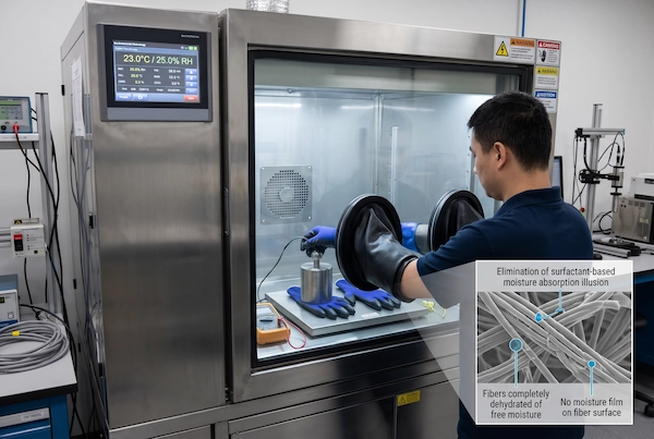
In-Situ Testing via Dedicated Glove Ports on the Test Chamber: To eliminate any possibility of secondary moisture absorption, the SQG Quality Inspection Laboratory employs walk-in/chamber-type environmental test systems equipped with fully sealed access flanges. The front door of the test chamber is integrated with two pairs of industrial-grade, sealed butyl rubber glove ports; quality control engineers can perform the entire measurement sequence inside the chamber by inserting their hands directly into the external isolation gloves without opening the main chamber door;
Closed-Loop Sealed Measurement SOP:
Test personnel operate the specialized mechanical fixtures inside the chamber through the isolation gloves, placing the test specimen flat on the pre-positioned Teflon (PTFE) high-insulation test plate within the chamber;
They gently press the chamber’s specialized 5-pound weighted concentric electrode onto the microporous-coated surface of the glove’s fingertips or palm;
The electrode leads are routed outside the chamber through a dedicated, ultra-high-insulation Teflon (PTFE) sealed wall-penetrating aviation connector on the side wall of the test chamber and connected directly to a high-precision external megohmmeter system;
Apply the test voltage and, within the chamber’s sealed microclimate—completely free from external convective interference—immediately read and record the stable surface resistivity;
Ensuring the authenticity and reproducibility of audit data: By completely enclosing the entire testing process within a “constant vacuum-level microenvironment” maintained at 23 degrees Celsius and 25% relative humidity (extreme dryness), the test thoroughly eliminates contamination of the test baseline caused by operator breath moisture, hand perspiration, and external workshop airflow fluctuations, thereby presenting third-party auditors with pure physical data that possesses absolute legal validity and engineering reproducibility.
Metrology & Fixtures: ANSI/ESD STM11.11 Concentric Ring Probe Testing
In metrological testing of the surface resistivity of anti-static gloves, the electrode topology and mechanical contact pressure of the test fixture directly determine the uniformity of the electric field distribution and the reliability of the impedance readings. Many small manufacturers or distributors arbitrarily use handheld dual-point parallel probes or pointed multimeter probes to directly apply pressure to the glove coating during factory inspections. Due to the minuscule point-contact area, the uncontrollable depth of probe penetration into the coating, and random fluctuations in the downward pressure applied by the operator, the measured data often contain human-induced discrete errors as high as several times the actual value. Automotive-grade superfactories strictly reject such crude testing methods and fully implement the metrological inspection procedures for concentric ring probes established in accordance with the ANSI/ESD STM11.11 standard of the American National Standards Institute (ANSI).

4.1 Concentric Ring Electrode Geometry and Surface Resistivity Calculation
The concentric ring electrode is recognized internationally in the field of electrostatic metrology as the reference-grade physical fixture for evaluating the surface resistivity of planar insulating and dissipative materials; its mechanical and geometric parameters are subject to strict calibration requirements:
5-pound standard weight and mechanical contact pressure distribution: The total weight of the test probe is strictly calibrated to 5 pounds (approximately 2.27 kilograms), and the entire probe is precision-machined from high-purity solid brass or stainless steel. The conductive contact surface at the bottom of the probe is lined with a layer of conductive silver adhesive or conductive silicone rubber padding approximately 6 millimeters thick, with a Shore A hardness strictly controlled between 50 and 70 degrees. When the weight is placed vertically and steadily on the surface of the glove under test, the combination of its standard weight and the elastic pad of a specific hardness completely eliminates interference from microscopic irregularities on the glove’s surface at the contact interface. This ensures that the microporous polyurethane (PU) coating or the fabric fibers on the back of the hand achieve complete molecular-level contact with the electrode under constant and uniform mechanical pressure, thereby eliminating the drastic drift in contact impedance caused by inconsistent manual pressure;
Calibration of the concentric ring electrode geometry: The standard electrode consists of two coaxial, concentric components—the inner disk electrode (Center Disk Electrode) and the outer ring electrode (Outer Ring Electrode):
The diameter of the inner disk electrode is strictly calibrated to 30.48 millimeters (1.20 inches);
the inner diameter of the outer ring electrode is strictly calibrated to 57.15 millimeters (2.25 inches), and the outer diameter of the outer ring is calibrated to 69.85 millimeters (2.75 inches);
an annular insulating gap 13.335 millimeters (0.525 inches) wide is formed between the inner and outer electrodes ;
Geometric integration conversion model for surface resistivity: In a ring-shaped electrode structure, current flows radially in a 360-degree circular pattern from the inner disk electrode along the glove surface toward the outer ring electrode. Based on Maxwell’s principle of two-dimensional planar integration of electromagnetic fields, the surface resistance value (Rs, unit: ohms) measured by a megohmmeter is converted to the material’s intrinsic surface resistivity (Rho_s, unit: ohms per square, Ohms/sq) using the following geometric correction factor formula: Geometric constant = 2 × pi (π) ÷ [natural logarithm (outer ring inner diameter / inner disk diameter)]. When the standard dimensions mentioned above are substituted into the calculation, this fixed geometric constant strictly equals 10.0. This means that, provided the glove material is isotropic, whether in the microporous coated area or the fabric mesh area on the back of the hand, the ohm reading measured by the instrument can be directly multiplied by 10 to accurately reflect the material’s true physical surface resistivity per unit square area, thereby eliminating the physical limitation of traditional two-point probes, which can only reflect a single local conductive path.
4.2 Dual-Voltage, Dual-Polarity Automated Megohmmeter Cycles
In addition to the geometric accuracy of the fixtures, the electrical characteristics of the test instrument’s output power supply are equally critical for accurately capturing the true insulation dissipation boundary. The precision digital high-resistance megohmmeter system configured on the SQG production line fully incorporates fully automated test cycles that comply with ESD standards, including “automatic dual-voltage range switching” and “dual-polarity reversal to eliminate polarization”:
10V and 100V automatic range-switching breakdown prevention logic: In static testing, consistently using a single high-voltage test often results in severe false-positive errors. When the glove under test is in a low-resistance conductive state (less than 1.0×10^6 ohms) or a critical transition state, directly applying a 100V high-voltage DC electric field can easily cause the strong electric field to break down microscopic air gaps on the material’s surface, generating transient micro-arc sparks. This results in a false reading of low resistance. The SQG intelligent megohmmeter executes a two-stage test sequence:
Stage 1 (10 V Low-Voltage Detection): The instrument first automatically performs a preliminary scan using a 10 V DC test voltage; if the measured resistance of the sample is below 1.0 × 10⁶ ohms, the system immediately locks onto the 10 V setting to complete the reading, protecting the material from arc breakdown;
Stage 2 (100 V High-Voltage Calibration): If the measured resistance reaches or exceeds 1.0 × 10⁶ ohms, the system will smoothly and automatically ramp up the voltage to a 100 V DC high-voltage electric field within 100 milliseconds to fully activate the barrier hopping of carbon fiber filaments within high-resistance dissipative materials, thereby accurately determining the material’s ultimate dissipative impedance when subjected to high-voltage charges;
Bipolar reversal to eliminate interference from dielectric polarization charges: When polymer polyurethane and synthetic polyester fibers are subjected to a continuous unidirectional DC high-voltage electric field, the dipoles within the material align in a specific direction and accumulate space charge at the electrode edges, forming a reverse self-induced electric field (dielectric polarization effect). This causes a continuous decay in current readings during the later stages of the test and a false rise in impedance. When performing standard measurements, the automatic megohmmeter strictly follows a closed-loop cycle: data is collected for 15 seconds with the forward voltage applied, the power is automatically shut off for 5 seconds to discharge the charge, and then the electrode polarity is reversed to apply the reverse voltage for 15 seconds, followed by another data collection. The system automatically calculates the geometric mean of the two resistance readings (one forward and one reverse) as the final reported value, completely neutralizing dielectric polarization errors and providing the production floor with an automotive-grade impedance baseline of absolute reliability.
Engineering Quality Assurance Matrix: SQG Factory Gatekeeping vs. Industry Baseline
In procurement and bidding processes for semiconductor packaging, new energy vehicle “three-electric” systems, and precision industrial control motherboards, the supply chain audit teams of multinational corporations are placing increasing emphasis on closed-loop engineering validation at the source of manufacturing. Low-cost traders and small OEM workshops often drive down their quotes by piecing together outsourced materials and renting makeshift workshops; their factory-exit inspections remain at a rudimentary stage, limited to “visual checks for no visible damage and the presence of a certificate of conformity on the outer packaging.” When such protective gloves enter automated SMT workshops, the lack of control over underlying physical metrics often leads to uncontrollable batch-level electrostatic breakdown and micro-contamination of solder pads during dry, cold seasons.
To quantitatively illustrate the dividing line between professional in-house manufacturing and OEM/private-label production in terms of quality engineering, the table below provides a comprehensive side-by-side comparison of key quality control checkpoints throughout the entire process.
Factory Metrology & Gatekeeping Benchmarking Table
| Quality Control Dimensions (QC Dimension) | Low-Cost Traders / Private-Label Workshops Standards | SQG Super Factory Standard Quality Access Control | In accordance with test standards (Standard) | Benefits of Quality Risk Mitigation |
| Incoming Quality Control (IQC) | Based solely on written certification from yarn suppliers | 100% Four-Probe Resistance Testing on Yarn Reels | ASTM F84 / Internal Control Procedures | Detect breaks and break points in conductive carbon filaments within batches |
| Temperature and Humidity Control in the Test Environment | Open workshop (typically above 50% RH) | 24-Hour Extreme Low-Humidity Chamber Conditioning (25% RH) | EN 16350 / IEC 61340 | Eliminate products that fraudulently use surfactants to simulate moisture absorption |
| Surface Resistance Test Fixture | Simple dual-probe handheld spot pressure gauge | 5-pound Calibrated Weight with Concentric Ring Electrodes | ANSI/ESD STM11.11 | Eliminate measurement errors caused by uneven manual pressure |
| Acceptable Quality Limit (AQL) | MIL-STD-105E Class II (AQL 4.0) | AQL 0.65 Rigorous and Stringent Sampling Standard | ISO 2859-1 / ANSI ASQ Z1.4 | Meets multinational semiconductor automotive-grade quality standards |
| System Ground Impedance (Rgp) | No actual test data; only nominal theoretical values | 100% Simulated Workstation Measurement While Worn | ANSI/ESD S20.20 | Ensure compliance with transient discharge requirements after operators put on protective gear |
| Full-Process Digital Traceability | Only generic model paper labels affixed to outer boxes | Laser-Engraved Encrypted Batch QR Code on Each Bag/Box | Industry 4.0 MES Traceability System | Scan to directly read raw material roll numbers, temperature and humidity data, and test lot information |
A Deep Dive into Tier-1 Engineering Safeguards
As shown in the comparison matrix above, the SQG Super Factory does not merely conduct simple tests at a single production stage; rather, it deeply integrates electrostatic physics with industrial manufacturing engineering to establish a six-tier engineering firewall that spans the entire process from raw materials to final shipment:
Intercepting broken-fiber dead zones at the raw material source: OEM workshops blindly trust the generic factory acceptance certificates issued by upstream yarn and chemical fiber manufacturers, making it impossible for them to detect microscopic internal fractures in conductive filaments caused during transportation or yarn winding; Upon arrival at the factory, SQG uses a four-probe tester to perform 100% continuous dynamic conductivity scans on every roll of raw yarn. This directly intercepts defective yarn rolls exhibiting resistance spikes before they reach the circular knitting machines, eliminating at the source the engineering flaw of localized insulation breaks in gloves;
Extreme drying and dehydration in a climate chamber shatter the illusion of moisture-absorption fraud: Conventional low-end products rely on a conductive film formed by water vapor in standard workshop environments—where relative humidity exceeds 50% RH—to pass inspections under pretenses; SQG strictly adheres to the EN 16350 protocol, placing test samples in an extreme drying chamber at 23 degrees Celsius and 25% RH for forced humidity control for over 24 hours. This thoroughly removes all unbound free water, forcing the material to rely solely on its internal polymer-based continuous carbon fiber network for charge dissipation, ensuring zero performance drift even in extremely cold, dry northern workshops or high-airflow cleanrooms;
Eliminating variability in manual contact pressure to achieve metrological-grade reproducibility: With lightweight handheld probes, downforce relies entirely on the inspector’s tactile sensation, resulting in significant fluctuations in penetration depth and contact area with each press, which easily leads to distorted readings; SQG introduces a concentric annular electrode strictly calibrated to a 5-pound weight, combined with a standard Shore-hardness conductive rubber pad, to lock the measurement pressure at the standard-specified value. Coupled with the Maxwell two-dimensional field integral algorithm, this system outputs surface resistivity parameters with metrological traceability and legal validity;
AQL 0.65 Rigorous Sampling Inspection Aligns with Automotive-Grade Zero-Defect Standards: The industry’s commonly adopted lenient AQL 4.0 standard permits a high defect rate within an entire batch of materials, posing extremely high risks for the assembly of high-unit-cost automotive domain controllers and radar sensors; SQG employs automotive supply chain-level AQL 0.65 stringent sampling inspections to minimize the probability of accepting non-conforming products to the absolute limit. Additionally, we conduct workstation-level actual measurements and verification of ground impedance (Rgp) under final wear conditions to ensure that every pair of gloves shipped provides a millisecond-level safe conductive closed loop when contacting the edges of sensitive circuit boards;
One-product-one-code traceability eliminates information blind spots in cross-border contract manufacturing: Handwritten or simple adhesive labels have been completely phased out, and encrypted Batch QR serial codes are laser-printed on the clean outer packaging of the ST-610, ST-300, and ST-310, as well as on the outer containers; Factory auditors need only scan the code to access the corresponding batch’s yarn lot number, knitting machine serial number, dynamic temperature and humidity curves during dipping, raw megohmmeter test data, and the electronic COA analysis report included with the shipment, enabling seamless, end-to-end quality traceability throughout the entire process.
Statistical Process Control (SPC): Resistance Gaussian Distribution & Cpk Targets
In the fields of semiconductor wafer foundry and high-end automotive electronics manufacturing, the key factor in determining whether a protective glove manufacturer is qualified to supply automotive-grade products lies in the level of digital sophistication of its Statistical Process Control (SPC). Traditional quality control often relies on the pass rate of single or double spot checks on finished products; this “post-inspection” model cannot eliminate potential resistance drift within a batch. A “super factory” that truly meets Tier-1 standards must transform surface resistance testing into a continuous stream of quantified distribution data and use mathematical statistical models to monitor discrete trends in production line process capability in real time, thereby intercepting any quality fluctuations that deviate from the optimal dissipation window at an early stage.
Normal Distribution Curve and Cpk ≥ 1.67 Quality Target
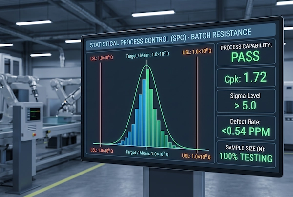
According to the ANSI/ESD S20.20 standard, the point-to-point resistance (Rp-p) of anti-static work gloves must fall within the electrostatic dissipative range of 1.0×10^6 to 1.0×10^8 ohms. In SQG’s digital manufacturing workshop, this range has been established as rigid tolerance limits: the Lower Specification Limit (LSL) is set at 1.0×10⁶ ohms (to prevent transient high-current discharges), and the Upper Specification Limit (USL) is set at 1.0×10⁸ ohms (to prevent charge accumulation and ensure insulation):
The Gaussian normal distribution converges closely: During high-volume continuous production, tens of thousands of sets of measured logarithmic resistance data collected by automated megohmmeters are plotted in real time as a Gaussian distribution curve. In contrast, small-scale workshops, due to uncontrolled coating viscosity and braiding tension, exhibit an abnormal distribution characterized by a flat, wide, and low-peaked curve—sometimes even with a bimodal distribution—where the troughs on both sides easily fall below the limit threshold. In contrast, the measured impedance distribution curve from the SQG production line exhibits an extremely narrow and highly concentrated single-peaked bell curve, with the mean strictly aligned with the theoretically optimal median value of 1.0 × 10⁷ ohms;
Process Capability Index (Cpk) locked at 1.67 or higher: To ensure an ultra-low defect rate of less than “0.54 parts per million” (ppm), the factory enforces the Process Capability Index (Cpk) as a mandatory quality threshold for each production stage. By minimizing the deviation of the process mean from the center of the tolerance specification and controlling dispersion using three times the standard deviation, SQG ensures that the measured Cpk for mass-production batches remains consistently stable at 1.67 or higher; this automotive-grade metric eliminates the risk of “edge classification errors” caused by random errors, ensuring that every box of gloves shipped from the factory falls well outside the low-resistance arc zone and the high-resistance insulation zone;
SPC Dynamic Trend Alerts and Adaptive Process Parameters: The MES traceability system monitors continuously collected resistance data using the Sigma (Σ) rule. If the mean impedance of seven consecutive random samples drifts unidirectionally toward the upper limit of 1.0 × 10⁸ ohms, the system will determine that this indicates an imbalance in coating curing or fluctuations in carbon fiber tension. It will immediately issue process adaptive adjustment commands to the dipping line, automatically fine-tuning the rheological viscosity of the dipping tank and the curing temperature of the drying oven to eliminate abnormal indicators in their infancy.
Impact of Coating Morphology: Uniformity in Finger-Dipped vs. Palm-Coated Gloves
The rheological behavior of polymer fluids under different dipping configurations presents distinctly different engineering challenges for controlling the uniformity of surface resistivity in finished gloves. During the immersion of the hand mold into the coating tank and the subsequent drainage and drying processes, finger-dipping and full-palm dipping exhibit different patterns of microscale coating thickness uniformity:
Tip-Dipping Process (Finger-Dipped): Tip Overhang Effect and Impedance Gradient: In the finger-dipping process, polyurethane (such as ST-300) is applied only to the tips of the five fingers. After the hand mold is inverted for dipping, the fluid—due to the combined effects of gravity and capillary surface tension—accumulates at the edges where the radius of curvature is extremely small at the fingertips, resulting in slight accumulation of coating material and droplet sagging. If the rheological viscosity of the coating is not properly controlled, the coating thickness at the very tips of the fingers will be significantly greater than that on the finger pads and lateral edges, leading to a discrete resistivity gradient across the surface of a single finger; SQG uses a servo motor to precisely control the lifting and rotational centrifugal angle of the hand mold, locking the coating thickness tolerance between the fingertip and finger pad to the micrometer level, ensuring uniform and consistent contact impedance at the fingertip during the assembly of micro-components;
Large-area leveling and micro-pore consistency in full-palm coating (Palm-Coated): Full-palm coating (e.g., ST-310) covers the entire palm, fingertips, and finger joints, with a coated surface area several times that of finger-only coating. During the process of continuous large-area film formation, the core challenge lies in preventing resin accumulation in the concave areas of the palm and bare spots at the outer edges; by utilizing a water-based polymer emulsion with excellent thixotropic properties combined with precise air knife sweeping, the full-palm coating forms a uniform, open-cell sponge-like microporous network during curing, maintaining extremely high spatial consistency in the impedance per unit area across the entire palm surface when in contact with an external antistatic mat;
Process Selection and Workstation Impedance Alignment Guide: To assist process engineers in precisely matching glove configurations to cleanroom classifications, airflow circulation conditions, and assembly motion stresses, we recommend thoroughly reviewing the specialized comparative literature Finger-Dipped vs. Palm-Coated ESD Gloves to gain a comprehensive understanding of the physical roles of these two coating methods in controlling surface resistivity, dynamic shear torque resistance, and particulate emission suppression.
Digital Traceability Architecture: Batch Serialization & Cryptographic COA
In the traditional trade of occupational safety gloves, a “Certificate of Analysis” (COA) is often nothing more than a static paper document bearing a red stamp and printed using a generic template, with test data that remains unchanged year after year—failing to reflect the actual electrical characteristics of the batch in question. For multinational electronics manufacturing service (EMS) giants and Tier-1 automotive electronics customers, unverifiable paper documents hold no audit credibility in supplier factory audits and quality traceability systems. Leveraging an Industry 4.0 digital Manufacturing Execution System (MES), SQG has comprehensively established a closed-loop digital traceability system spanning individual inner packaging, secondary packaging, and corrugated outer boxes, ensuring that the physical properties of every anti-static glove are firmly linked to the underlying database of actual test results.
Carton-Level and Polybag Laser-Etched Batch QR Codes
To prevent batch mix-ups, diversion of goods, and the substitution of substandard materials during supply chain transit, SQG has fully implemented an encryption-algorithm-based “one product, one code” batch serialization coding mechanism across its core product lines—including the 18-pin high-density anti-static ST-610, the finger-dip ST-300, and the full-palm micro-perforated dip-coated ST-310:
Laser cold-etching on clean packaging bags and outer cartons: We have eliminated traditional paper-based thermal adhesive labels, which are prone to peeling, curling, or releasing adhesive particles in cleanrooms. When inner liners—having been washed with purified water and dried—enter the clean packaging process, industrial-grade UV laser cold-etching marking machines installed on the production line directly etch high-resolution, encrypted two-dimensional matrix codes (Batch QR Codes) in situ onto designated anti-counterfeiting areas of the clean, anti-static inner packaging composite bags (polybags) and five-layer reinforced corrugated master cartons;
Multi-level Packaging Topological Binding and Batch Number Uniqueness: The coding system employs a hierarchical parent-child code association algorithm, establishing a dynamic topological binding in real time between the carton-level barcode on each outer carton and the serial numbers of the dozens of inner polybags it contains. Each QR code not only contains the product’s basic model and dimensions but also embeds an anti-counterfeiting key generated from the production line number, the weaving team member ID, the resin coating batch timestamp (accurate to the second), and a dynamic hash function, thereby physically realizing the “one code per carton, one code per bag” unique serialization authentication;
Chemical-Resistant Wiping and Cleanroom Compliance: Laser micro-engraving acts directly on the surface of the packaging film material without introducing any external inks or solvent-based coatings, thereby eliminating secondary air pollution in cleanrooms caused by heavy metals or volatile organic compounds (VOCs) found in conventional printing inks. Even after repeated wiping of the outer surface with 75% medical-grade isopropyl alcohol (IPA) or deionized water, the QR code remains clear and sharp, ensuring long-lasting machine-readable legibility in the harsh material handling and disinfection environments of electronic manufacturing cleanrooms.

Cloud-Accessible Certificate of Analysis (COA) Dossiers
The core value of digital traceability lies in completely eliminating “information blind spots” during factory audits. When SQA engineers, quality control managers from multinational corporations, or third-party independent auditors conduct on-site inspections, they no longer need to retrieve lengthy, manually maintained paper ledgers. Instead, they can simply use a smartphone or industrial handheld PDA to scan the encrypted batch QR code on the packaging, instantly accessing the cloud database to view the complete quality testing dossier covering the entire lifecycle of that batch of gloves:
Retrieve the original temperature and humidity curves from the 25% RH extreme drying chamber: The system provides an intuitive, continuous monitoring line graph showing the entire EN 16350 humidity conditioning process performed on the batch’s sampled products within the constant temperature and humidity test chamber. Auditors can verify whether the temperature in the humidity-controlled chamber was maintained at 23 degrees Celsius (tolerance ±1 degree) throughout the 24-hour pre-treatment cycle, and whether the relative humidity was consistently controlled at the 25% RH limit (tolerance ±3%), thereby eliminating any loopholes related to insufficient dehydration time or environmental moisture manipulation;
Raw grid-based data set from actual megohmmeter measurements: The cloud-based COA eliminates vague “pass/fail” conclusions and directly discloses the raw data matrix collected during the 5-pound concentric ring electrode test for that batch of gloves (including point-to-point resistance Rp-p and surface resistivity). The page comprehensively lists the real-time readings at each test point for both 10V low-voltage detection and 100V high-voltage calibration, the mean values before and after polarity reversal, as well as the mean and three times the standard deviation automatically fitted via a Gaussian distribution. This provides the audit team with a clear understanding of the actual convergence of the entire batch within the 1.0×10⁶ to 1.0×10⁸ ohm range;
Fourier-Transform Infrared Spectroscopy (FTIR) and Ion Chromatography Chemical Purity Reports: In addition to electrical specifications, the digital batch file includes FTIR spectra and ion chromatography chemical purity reports for each batch of polyurethane coating, determined by an independent third-party laboratory or the factory’s quality control center prior to shipment. Auditors can access FTIR spectra with a single click to verify whether the baselines at the key siloxane characteristic peaks at 1260 cm⁻¹ and 800 cm⁻¹ are flat (confirming the absence of free silicone oil release agents) and download the test results for the detection of residual trace harmful ions—such as chloride ions (Cl⁻), sodium ions (Na⁺), and sulfate ions, among other trace harmful ions,-from ion chromatography tests. With concrete, end-to-end physical, chemical, and electrical data, this provides conclusive engineering validation for the release of incoming materials for high-end automotive electronic control units and semiconductor production lines.
Tier-1 Vendor Audit Checklist: Step-by-Step On-Site Verification SOP
During on-site vendor audits for automotive chip assembly and high-precision microelectronics anti-static equipment, senior quality control auditors from multinational electronics manufacturing services (EMS) groups and Tier-1 customers do not merely sit in conference rooms listening to PowerPoint presentations; instead, they go directly into quality inspection laboratories and packaging cleanrooms to carry out “real-world, hands-on” standard operating procedure (SOP) verifications. To help procurement teams and third-party compliance audit teams establish a standardized, reproducible baseline for on-site verification, SQG Super Factory has compiled and released a comprehensive on-site audit checklist for automotive-grade anti-static glove suppliers, focusing on two critical defense lines: the physical traceability of metrology instruments and real-time blind sampling and retesting on the production line.
Metrology Calibration Records & NIST Traceability Verification
The authority of test data is entirely based on the physical traceability chain of metrological testing equipment. The first action an auditor takes upon entering the factory’s physical laboratory is to trace the qualifications of all instruments used for factory release testing:
Verification of dual traceability chains to the National Institute of Metrology (NIM) and NIST:
On-site verification of the valid calibration periods for all high-precision digital megohmmeters in use. Instruments must possess authoritative third-party metrological calibration certificates issued by the National Institute of Metrology (NIM) or traceable to the National Institute of Standards and Technology (NIST);
Strictly investigate testing equipment that has “exceeded its service life” or has only internal “self-calibration records” from the manufacturer, ensuring that the output voltage accuracy error of the test unit is strictly controlled within ±1% in both the 10V low-voltage and 100V high-voltage ranges, and that the measurement resolution for weak leakage current reaches the picoampere (pA) level;
On-site re-inspection of the geometric dimensions and mechanical downward force of the 5-pound weight’s concentric circular electrodes:
The auditor uses a micrometer to measure the geometric dimensions of the inner and outer rings of the concentric circular electrodes on-site, verifying that the inner ring diameter is exactly 30.48 millimeters and the inner diameter of the outer ring is 57.15 millimeters, ensuring that their converted geometric constant strictly corresponds to 10.0;
Use a calibrated electronic balance to weigh the total mass of the test weight on-site; it must fall precisely within the 5-pound (approximately 2.27 kilograms) standard weight range (tolerance of ±2%);
Use a Shore hardness tester to measure the elastic hardness of the conductive silicone rubber layer on the bottom surface of the electrode, confirming that it remains within the standard elasticity range of 50 to 70 degrees Shore A. Additionally, use a megohmmeter to remeasure the resistance value of the electrode pad itself (which must be less than 1,000 ohms) to eliminate system test errors caused by electrode aging, hardening, or a reduction in contact area;
Verification of environmental temperature and humidity sensor channel comparisons and dynamic temperature and humidity calibration certificates:
Review the annual inspection certificate for the integrated temperature and humidity sensors in the 25% RH extreme dry test chamber;
The auditor uses a portable third-party handheld calibration thermometer and hygrometer to perform an in-situ three-point comparison of temperature and humidity through the test chamber’s access port, verifying that the deviation between the internal monitoring readings and the external reference instruments is within ±0.5 degrees Celsius for temperature and ±1.5% RH for relative humidity, thereby eliminating any potential for “hidden cheating” caused by sensor reference drifts.
Live Unboxing & Blind Sampling Protocol on the Packaging Line
Any “Golden Samples” pre-prepared by the factory are not representative for audit purposes. On-site verification in accordance with Tier-1 specifications must be conducted by auditors through unannounced, randomized “Live Unboxing & Blind Sampling” tests on the production line:
Unannounced Blind Sampling at the End of the Cleanroom Packaging Line and Batch Freezing:
Without prior notice, the auditor walks directly to the end of the ISO 5 / Class 100 cleanroom packaging area;
From the ST-610, ST-300, or ST-310 finished product batches currently undergoing box packing and sealing on that day, the auditor personally selects three sealed outer boxes from three different pallets at random, breaks the sealing tape on the spot, and randomly extracts two sealed inner bags—each with completed laser coding—from the top, middle, and bottom layers (for a total of six test samples). The MES system then immediately freezes the release authorization for that production batch on-site;
Zero-Exposure Transport and Accelerated Pre-Treatment in an Extreme-Condition Drying Chamber Before Storage:
The blind test samples are transported directly to the physical quality inspection laboratory under the auditor’s full supervision;
After removing the outer protective bag, the glove samples are immediately laid flat and suspended inside a constant-temperature and humidity chamber maintained at a steady state of 23 degrees Celsius and 25% RH;
During routine rapid factory audits, the system activates “rapid dehydration and purging mode” and maintains a constant temperature and humidity microcirculation for at least 4 hours to forcibly evaporate free environmental moisture from the glove surface, thereby accelerating the exposure of the material’s intrinsic electrical properties;
Closed-Loop Isolation Chamber In-Situ Blind Testing and Sign-Off Process:
Upon completion of pretreatment, the auditor personally, or a lab technician under the auditor’s full-process video supervision, inserts both hands into the environmental chamber through the sealed glove ports to perform in-situ testing without opening the chamber door;
Lay the gloves under test flat one by one on a Teflon insulating board, press down the 5-pound hammer electrode, and perform bipolar, dual-voltage megohmmeter measurements on the glove’s fingertips, the microporous areas of the palm coating, and the intersecting points of the conductive carbon fiber warp and weft on the back of the hand;
Real-time data was collected, and point-to-point resistance values were transcribed onto the audit report to verify that all measured values for each group strictly fell within the anti-static safety dissipation range of 1.0×10⁶ to 1.0×10⁸ ohms;
Conduct on-site cross-checks of randomly selected test data against the raw batch COA data from the cloud, retrieved by scanning the laser-engraved QR code on the outer packaging; Once data consistency is confirmed, the auditor and the factory’s Quality Director jointly sign the paper and digital factory audit release forms on the spot, completing a rigorous, real-world quality closed-loop verification.
Frequently Asked Questions (FAQ)
Why do non-compliant ESD gloves pass initial factory audits but fail after 90 days?
In the electronics manufacturing industry, many ESD gloves that have not undergone rigorous certification can “slip through” factory inspections or initial factory audits because they rely on low-cost surface-active agents (such as quaternary ammonium fatty acid salts) that are sprayed or dipped onto the surface to enhance moisture absorption:
Mechanism of spontaneous decay and volatilization of the surface water film: These surfactants essentially rely on hydrophilic groups to forcibly adsorb water molecules from the air, forming a temporary hydrated, ionically conductive water film on the glove’s outer layer; however, these surfactant molecules adhere to the fiber surface only through weak physical van der Waals forces and do not form strong covalent bonds with the base material; During storage and distribution after the finished product leaves the factory—over a period of approximately 90 days—the surfactant molecules naturally volatilize, migrate toward the inner layers, or oxidize and precipitate due to air convection, temperature fluctuations, and adsorption by packaging materials;
Irreversible damage caused by physical friction and washing: Once the gloves are put into service, the extremely thin surfactant layer is worn away and peeled off within a few hours due to the mechanical shear forces generated by workers’ frequent contact with components and shipping containers; If washed with deionized water in a cleanroom, these water-soluble additives will be completely rinsed away, causing the glove’s surface resistivity to surge exponentially to over 1.0×10^10 ohms, rendering it a high-risk insulator;
The advantage of a physical carbon fiber skeleton’s consistent lifespan: In contrast, automotive-grade products such as the ST-610, ST-300, and ST-310 rely entirely on a network of bicomponent continuous carbon fiber filaments embedded within the inner liner for their conductive pathways. Charge transfer is based on the physical transition of delocalized free electrons within the carbon atomic lattice and does not depend on any environmental moisture molecules. These products possess intrinsic properties of resistance to chemical cleaning, physical wear, and aging; even after continuous use for several months under severe operating conditions, their point-to-point resistance remains consistently within the standard electrostatic dissipation range.
What is the mechanical difference between a 5-lb concentric ring probe and two-point probes?
In the physical measurement of surface impedance, different test fixtures exhibit fundamental engineering differences in charge distribution models and mechanical contact area:
Limitations of traditional two-point probes: Two parallel electrodes typically consist of two small cylindrical rubber blocks placed parallel to each other. Their contact area is narrow and forms only a unidirectional linear electric field; the impedance value measured by the instrument during testing represents only the local path with the lowest resistance between the two contact points, making it completely incapable of detecting impedance fluctuations in other directions caused by glove coatings. Furthermore, handheld two-point probes rely entirely on manual pressure applied by the operator, with applied force ranging from 1 to 3 pounds. Fluctuations in pressure can cause discrete errors in the contact area that vary by a factor of several, resulting in data that lacks reproducibility and metrological authority;
Mechanical and Geometric Advantages of the 5-Pound Concentric Ring Probes: Designed in accordance with the ANSI/ESD STM11.11 standard, these concentric ring electrodes are precisely calibrated to a total weight of 5 pounds (approximately 2.27 kilograms). Pressure is applied vertically by gravity, eliminating impedance drift caused by variations in manual pressure depth;
Degree Isotropic Electric Field Integration: The concentric ring probe consists of a central disk electrode and an outer concentric ring. When the probe is pressed down, it induces a 360-degree, outward-radiating, symmetrical electric field across the glove’s surface. The measured surface resistance readings, after being converted using a geometric correction factor based on circumferential integration, accurately reflect the comprehensive surface resistivity per unit square area of the tested region; Whether it is the distribution of microcells within the microporous polyurethane coating or the interwoven grid of conductive carbon filaments, any broken wires or localized dead zones in any direction will be clearly revealed in the concentric circular electric field, thereby providing a rigorous physical quantification of the glove’s antistatic dissipation capability.
Why is 24-hour conditioning at 25% RH mandatory for ESD cleanroom PPE?
In ISO cleanrooms and modern SMT assembly facilities, placing anti-static personal protective equipment (PPE) in a low-humidity chamber maintained at 23 degrees Celsius and 25% RH for 24 hours of mandatory pre-conditioning is a mandatory engineering control designed to eliminate “environmental moisture cheating”:
A real-world scenario of extreme dryness in cleanrooms during winter: In northern regions during winter or in semiconductor cleanrooms with extremely high fresh air exchange rates, the constant temperature and humidity circulation system—designed to control particulate contamination and suppress condensation—often causes the relative humidity at specific workstations to plummet to 30% RH or even below 25% RH; If protective gloves are only conductive under conventional high-humidity conditions of 50% to 60% RH, they will suddenly fail in actual dry production lines, creating fatal electrostatic blind spots that can cause chip breakdown;
Complete removal of free moisture and intrinsic material testing: The micropores within polymer materials possess the ability to capillarily adsorb water vapor; only through 24 hours of continuous deep dehydration and pre-conditioning in an ultra-dry chamber at 25% RH can all non-bound free water molecules trapped in the micropores of the glove coating and the gaps between fibers be completely evaporated; This process forcibly strips away the pseudo-conductive ionic water film formed by atmospheric humidity, forcing the gloves to reveal the true electrical performance of their internal, purely physical conductive grid; only products that withstand this low-humidity test and maintain a resistance value below 1.0×10⁸ ohms possess the investment-grade quality required to continuously protect precision chips under all-weather conditions and across seasonal climate fluctuations.
How does SQG maintain a Cpk of ≥ 1.67 across large production volumes?
In large-scale industrial manufacturing with an annual output of tens of millions of pairs, to consistently and stably maintain the process capability index (Cpk) at 1.67 or higher (meaning a defect rate within tolerance limits of less than 0.54 per million), SQG relies on end-to-end automation and a physical closed-loop control mechanism:
Fully automated online metering and dispersion system for conductive carbon black masterbatch: In the rubber compounding preparation stage, traditional manual batching methods have been eliminated in favor of fully enclosed, high-shear dynamic dispersion reactors and online ultrasonic emulsification technology; The system integrates high-precision mass flow meters to perform milligram-level closed-loop continuous automatic blending of water-based polyurethane resin and nano-conductive carbon black masterbatch, ensuring that fluctuations in the solid-phase volume ratio of the conductive phase within the rubber compound remain within ±0.3%, thereby locking in the baseline viscosity and intrinsic conductivity at the chemical source;
Non-contact online laser thickness measurement and micrometer-level adjustment of immersion depth: The hand mold production line is equipped with high-frequency, multi-axis non-contact laser thickness sensors and a machine vision array; during the immersion and withdrawal of the hand mold, the thickness measurement system scans the wet and dry film thicknesses of the polyurethane microporous coating layer at a refresh rate of microseconds; As soon as a deviation in the thickness of the resin layer on the fingertips or palm is detected, the control center dynamically fine-tunes the hand mold’s tilt angle, lifting acceleration, and immersion time via servo motors within a few milliseconds, ensuring that the thickness of the microporous coating across the entire palm strictly converges within the preset tolerance range;
Constant-Tension Continuous Filament Weaving and Real-Time Melt-Cutting of Warp and Weft Breakages: In the knitting workshop, fully automated computerized glove knitting machines are equipped with highly responsive piezoelectric micro-force tension sensors; the yarn feeding mechanism maintains a constant micro-tension output in the tens of millinewtons (mN) range at all times, eliminating mesh deformation caused by uneven tension; Simultaneously, an infrared optical break detection system scans the warp and weft knitting points at a frequency of several hundred times per second. If even a single conductive carbon filament breaks, the knitting machine will automatically brake, stop, and trigger an alarm within 5 milliseconds, preventing defective gloves from entering subsequent processes at the source. This ultimately ensures that the measured resistance data of large batches of finished products is highly concentrated at the center of the Gaussian distribution curve.
Closing & Engineering Specification Advisory
In the fierce competition among top-tier supply chains in the global semiconductor and new energy vehicle electronics industries, “Zero Defects” has never been just an empty quality slogan—it is a hard engineering capability built on end-to-end physical measurement instruments, Statistical Process Control (SPC), and tamper-proof digital records. While low-end contract manufacturers and traders still rely on surfactants to falsely report impedance under standard humidity conditions, leading superfactories have long pushed the boundaries of anti-static control to a closed-loop system featuring dryers operating at the extreme limit of 25% RH and 5-pound concentric electrode measurements.
As flagship protective equipment specifically designed for automotive-grade chip mounting and ultra-precise SMT workstations, the ST-610—featuring an 18-pin ultra-high-density nylon and two-component continuous conductive carbon fiber composite liner, an ultra-thin water-based microporous conductive coating, and a Gaussian single-peak impedance distribution consistently converging between 1.0×10⁶ and 1.0×10⁸ ohms—eliminates latent breakdown risks on automated production lines. To view the complete set of ANSI/ESD STM11.11 concentric circle surface resistance test arrays for this batch, access the temperature and humidity monitoring curves for 25% RH limit dehydration, and review the full FTIR silicone-free testing records, or to request production line verification samples for your company’s international vendor audit, please visit the ST-610 18-Gauge Antistatic Glove dedicated specifications and sample request page (https://sqgsafety.com/product/st-610/).