

Introduction: The Mechanical-Electrical Paradigm in ESD Textile Engineering
In microelectronics manufacturing and semiconductor cleanroom processes, the use of carbon fiber conductive yarn ESD gloves to establish microscopic charge dissipation pathways directly determines the actual protective limit of an entire precision SMT assembly line against electrostatic overstress (EOS) and invisible hard discharges. Many Quality Engineering (QE) teams at major electronics manufacturing service (EMS) providers and chip packaging facilities commonly face an extremely insidious technical pitfall in their daily quality control: when surface resistance is statically measured using a high-resistance meter during the Incoming Quality Control (IQC) stage, all data for a batch of newly procured anti-static gloves fully comply with standards; however, just two to three weeks after these gloves are deployed at high-cycle-rate assembly stations, production lines experience a surge in CMOS logic deadlocks and MOSFET gate dielectric breakdown failures. Upon retesting on-site, the local resistance in the stress-concentrated areas of the knuckles—where the gloves were originally deemed compliant—has already skyrocketed to over 10^11 ohms, effectively transforming them into high-resistance insulators.
The root cause of this batch-wide anti-static failure lies in the supply chain’s failure to account for the physical damage caused by dynamic mechanical deformation to the electrically conductive network during the product selection process. A large number of low-cost work gloves on the market are essentially conventional insulating synthetic fiber fabrics; their claimed “anti-static” performance often relies solely on the external spraying of quaternary ammonium salt surfactants or the use of discontinuous short-fiber blends with extremely low proportions and loose spacing. When subjected to high-frequency finger joint bending and stretching—occurring thousands of times daily—as well as friction against material edges and cleaning with deionized water in cleanrooms, the chemical coating on the surface of these products rapidly dries out and peels off. This causes the microscopic conductive network to fracture physically, resulting in the complete collapse of the original charge dissipation pathways.
From the perspective of textile structural physics, the long-term reliability of microelectronics-grade anti-static gloves has never been a simple matter of adding a chemical coating, but rather a rigorous mechanical-electrical topological engineering endeavor. Whether a glove can withstand mechanical fatigue throughout its entire lifecycle depends on the gauge of the inner lining’s weave, the cross-linking strength of the base composite fibers, and the density of the permeable mesh formed in three-dimensional space by micron-scale bicomponent conductive carbon fiber filaments. Only by embedding an intrinsically conductive network into the woven framework at the molecular level can the gloves maintain millisecond-level dynamic charge dissipation capabilities even under severe bending and deformation. For engineering and procurement teams currently restructuring cleanroom ESD defense systems and investigating potential breakdown hazards at workstations, we recommend first thoroughly reviewing our industrial-grade material architecture, which has been rigorously validated through real-world testing: Antistatic (ESD) Gloves.
H2 (1): Microstructural Anatomy: Bicomponent Conductive Core Filaments
In precision electronics assembly and semiconductor cleanrooms, the durability of antistatic liners depends on the microstructural cross-sectional engineering of individual conductive fibers. Many procurement teams mistakenly believe that simply having metal or carbon components in the fiber is sufficient to provide protection, overlooking the physical form in which the conductive phase exists within the polymer matrix. If the conductive material relies solely on surface adsorption or plating, its conductive pathways are highly susceptible to physical breakdown under the dual stress of mechanical strain and chemical cleaning.
H3: Core-Sheath vs. Matrix-Fibril Extrusion Technology
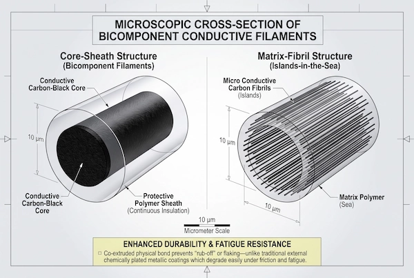
High-performance composite conductive filaments (Bicomponent Conductive Filament) used in high-end cleanroom gloves are produced during the melt spinning stage by co-extruding a blend of conductive polymers and conventional engineering plastics through a precision microporous spinneret. This process primarily results in two types of microscopic cross-sectional geometries:
Core-Sheath Architecture: This structure features a polymer matrix (such as polyamide or polyester) homogeneously filled with high-purity, nanoscale conductive carbon black as the core, completely encased by a continuous, dense, carbon-free insulating polymer sheath. This coaxial coating process tightly encapsulates the conductive carbon network within the fiber core, ensuring axial charge transport while eliminating the risk of carbon particles shedding into the cleanroom air and causing contamination;
Island Structure (Matrix-Fibril Architecture): Within the matrix polymer (matrix phase), dozens of nanoscale continuous microfibrils (island phase) highly filled with conductive carbon black are dispersed through a porous composite spinning process. These fine conductive channels extend parallel to the longitudinal axis of the fiber; even if the fiber’s surface undergoes minor abrasion due to heavy friction, the deep, unexposed “microfibril network” continues to maintain a continuous and unobstructed charge dissipation path;
Comparison of Melt-Cured Nano-Carbon Black with Metal-Plated Filaments: Traditional, low-cost conductive gloves often feature an outer layer of chemically electroplated silver or copper filaments. These metal coatings have a significantly different coefficient of thermal expansion from the synthetic fiber substrate and are highly prone to blackening and degradation due to salt spray corrosion from workshop sweat and air oxidation. More critically, the plating is highly prone to developing microscopic cracks and flaking off in patches under repeated bending. In contrast, intrinsically conductive filaments—in which nano-carbon black particles are permanently embedded within the polymer lattice via melt co-extrusion technology—are completely immune to chemical oxidation and flaking, exhibiting extremely high physical stability throughout their entire service life.
H3: Flexural Fatigue Resilience at Knitted Junctions
When production line workers handle components, operate power tools, or plug in and unplug test connectors, the knuckles of their gloves are subjected to extremely high-frequency bending:
Microscopic shear and tensile strains at warp-weft interlacing nodes: In seamless knitted gloves, conductive fibers are interlaced in the form of micrometer-scale loops (Knitted Loops). Every time a worker clenches or opens their fist, the fibers at these interlacing nodes are subjected to severe multiaxial tensile forces, relative slippage, and repetitive shear stresses. The cumulative effect of thousands of bending cycles per day at a single workstation subjects the fibers to severe high-cycle flexural fatigue testing;
Hidden hazards of localized micro-arcs triggered by brittle fracture of inferior fibers: Short fibers or metal wires with low elongation—commonly used as conductive fillers—lack sufficient toughness. Under high-frequency shear fatigue, the conductive pathways at the interlacing nodes can rapidly develop lattice fatigue cracks and mechanical micro-fractures. This microscopic fracture causes the continuous closed-loop network to disintegrate into discontinuous, isolated nodes; when residual charges accumulate at both ends of the fracture micro-gap, creating a transient potential difference, it is highly likely to induce localized micro-discharges invisible to the naked eye, generating transient over-electric stress that directly causes breakdown of nearby highly sensitive chip pins;
Fatigue-resistant locking of lattice integrity by intrinsic composite filaments: High-quality bicomponent composite filaments possess exceptional dynamic fatigue resistance due to the elastic synergy between a high-toughness polyamide or polyester outer layer and an inner carbon black conductive network. Even after undergoing hundreds of thousands of bending cycles, the microscopic interfaces at the interlaced loop nodes remain tightly interlocked, preventing both the delamination of conductive filaments and core breakage, as well as lattice dislocation fractures, thereby completely eliminating dead zones for electrostatic accumulation caused by fatigue-induced open circuits.
H2 (2): Percolation Theory: Constructing 3D Isotropic Conductive Grids
Many procurement and quality engineering professionals often fall into the misconception that the electrical conductivity of anti-static fabrics is simply and linearly proportional to the proportion of conductive fibers added. In reality, within the microscopic structure of knitted composite materials, the transition from an insulating polymer matrix to a conductive continuous state follows the percolation theory. Only when the composite conductive filaments reach the statistical limit of geometric contact within the three-dimensional knitted network does the macroscopic impedance experience an exponential drop; if this critical threshold is not exceeded, sporadically doped conductive filaments alone are simply incapable of forming a homogeneous protective barrier on the production line. Regarding the decay kinetics of microscopic charges and the evolution of electric fields before and after reaching the percolation threshold, we have provided a detailed derivation in a previous physics monograph: “Surface Resistance and Charge Decay.”
H3: Critical Percolation Thresholds in Knitted Matrices
Within seamless knitted fabrics, polymer filaments such as polyester or nylon are inherently highly insulating media (with a resistivity greater than 1.0 × 10¹² ohms), whereas bicomponent carbon fiber filaments serve as highly conductive pathways:
Percolation thresholds and nonlinear transition points in resistivity: When the volumetric doping fraction of conductive fibers is extremely low, the conductive filaments are physically isolated in space by a large number of insulating matrix fibers, and the macroscopic resistivity of the system remains high; As the volume fraction of conductive fibers continues to increase during the knitting process and reaches a specific critical volume fraction—that is, the percolation threshold—an infinitely connected network of conductive filaments forms for the first time within the three-dimensional knitted structure; At this point, the fabric’s macroscopic resistivity experiences a precipitous drop within an extremely narrow doping range, plunging directly from the highly insulating region to the controlled dissipation range of 1.0 × 10⁶ to 1.0 × 10⁸ ohms;
Discontinuous bottlenecks and impedance discontinuities below the critical threshold: To cut costs, many low-quality gloves intentionally reduce the blend ratio of conductive fibers to below the percolation threshold; in this subcritical state, only scattered, isolated local clusters of conductivity can form within the fibers, separated by micron-scale insulating gaps; This directly results in the electrical impedance of the finished gloves exhibiting extremely unpredictable variability—while impedance measured at certain test points where fibers overlap densely may appear to comply with standards, in critical gripping areas such as the fingertips and palms, resistance can easily surge to over 10^10 ohms;
Risk of conductive network disruption due to workwear deformation: The knitted base fabric in a subcritical state is extremely fragile; once the glove is worn by a worker and undergoes elastic stretching, the originally weakly overlapped edge nodes are physically pulled apart, causing the barely connected conductive pathways to collapse instantly. This results in the anti-static protection on the production line being instantly rendered ineffective during actual assembly operations.
H3: Grid Pitch Geometry: 3mm Micro-Grids vs. 10mm Conventional Stripes
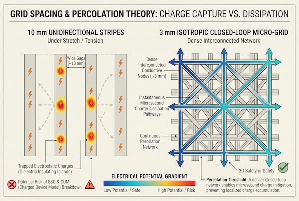
In addition to the volume doping ratio, the weaving geometry and grid pitch of the conductive filaments in the glove liner directly determine the reaction speed and spatial uniformity of charge capture:
Anisotropic Defects in 10-mm Conventional Unidirectional Wide Stripes: Standard anti-static gloves often feature a weave pattern of unidirectional parallel stripes spaced 10 mm or even 15 mm apart; This coarse layout exhibits severe geometric electrical anisotropy: charges can conduct along the longitudinal direction parallel to the stripes, but in the transverse dimension perpendicular to the stripes, charges must traverse a purely insulating polyester gap as wide as 10 mm; According to the laws of slow surface diffusion of charge at insulating interfaces, triboelectric charges cannot jump laterally to conductive lines within milliseconds, causing charges to remain trapped in the gaps between stripes for extended periods;
High-Density Charge Capture Mechanism via a 3-Millimeter Isotropic Micro-Grid: High-specification ESD gloves utilize a bidirectional interlocking weave in both warp and weft directions, strictly compressing the spacing to within 3 millimeters to form a homogeneous three-dimensional micro-grid; Within this 3-millimeter micro-grid architecture, the physical distance between any point on the glove’s surface and the nearest conductive filament is strictly limited to within 1.5 millimeters; when contact-separation charges are generated upon fingertip contact with a bin or tray, the charges do not need to undergo a lengthy lateral migration but are captured by the surrounding conductive grid within microseconds and rapidly diverted;
Eliminates surface dielectric micro-islands: The blank insulating areas between 10-millimeter-wide stripes behave microscopically like independent miniature energy-storage capacitors, making them highly prone to forming high-potential “dielectric micro-islands”; When an operator’s finger hovers over sensitive components, the accumulated charge on these micro-insulating islands induces strong, non-uniform mirror charges and induced electric fields on the chip pins, directly triggering dielectric breakdown under the Charged Device Model (CDM); In contrast, a continuous micro-grid with a spacing of less than 3 millimeters eliminates large areas of insulating dead zones, endowing the entire glove with highly homogeneous, isotropic dissipation characteristics and eliminating the risks of charge accumulation and near-field induction at the geometric source.
H2 (3): The Workhorse Architecture: 13-Gauge Carbon-Polyester Liners
In modern industrial-grade electronics manufacturing and cleanroom operations, 13-gauge carbon-fiber-reinforced polyester liners have long been regarded as the cornerstone architecture for balancing mechanical toughness and electrostatic control. Unlike low-gauge products that prioritize excessive thinness at the expense of durability, the 13-gauge medium-thickness weave maintains both the integrity of the physical protective barrier and the three-dimensional conductive pathways, providing stable support for production lines subjected to prolonged exposure to high mechanical friction.
H3: Synergy Between 13-Gauge Structural Ruggedness and Cut Resistance
The reason the 13-gauge braided system has become the standard configuration for most industrial assembly stations stems from its mechanical balance between fiber density and physical strain resistance:
High tensile strength and tear-resistant base made of continuous polyester filaments: The 13-gauge liner uses high-polymerization-degree continuous polyester filaments as its primary load-bearing structure. Compared to short staple fibers, which are prone to wear and pilling, high-strength continuous filaments provide a dense, interlocked fiber structure. This delivers exceptional tensile strength and tear resistance when subjected to minor burrs on sheet metal or sharp edges on circuit boards, significantly extending the service life of the gloves before they become unusable due to mechanical damage;
Precision bundled twisting ensures fatigue-resistant locking of the conductive filaments: During the spinning and weaving stages, bicomponent conductive carbon fiber filaments and polyester filaments undergo a high-density twisting composite process under constant tension, resulting in their tight encapsulation and interlocking within the main yarn bundle. This coaxial interlocking structure provides a robust mechanical buffer when the fibers are subjected to axial tensile and shear strains, preventing the conductive filaments from slipping, pulling out, or breaking locally during glove flexing, thereby ensuring that the conductive network maintains continuous physical overlap even under heavy-duty operations;
Low dust generation and filament anti-pilling control: The dense 13-needle filament structure eliminates the problems of shedding and breakage common in traditional staple fibers, significantly reduces the dispersion of microscopic lint caused by high-frequency friction at workstations, and effectively prevents particulate contamination of high-grade cleanroom work surfaces.
H3: ST-300 Finger-Dipped Design for Breathable Cleanroom Handling
For high-precision workstations that require frequent use of fine finger movements to handle tiny components, the ST-300 with its finger-dipped configuration offers a targeted ergonomic design:
13-needle carbon-polyester liner with microporous PU dip-coating on fingertips: The ST-300 features an ultra-thin, microporous polyurethane (PU) coating applied only to the distal joints and fingertips of all five fingers, while the palm and back of the hand remain fully exposed, retaining the 13-needle carbon-fiber conductive knit base. The coated fingertips ensure a non-slip grip and resistance to fingerprint smudges when handling small screws, connecting or disconnecting flexible printed circuits (FPCs), or using tweezers to grasp silicon wafers;
Microclimate sweat regulation on the bare-fabric palm: For workers engaged in high-intensity assembly tasks around the clock, sweaty palms are a major source of discomfort due to the accumulation of heat and moisture inside the gloves; The ST-300’s bare-fabric palm offers exceptional breathability and moisture-wicking performance; air circulates unimpeded through the knit’s micro-pores, maintaining the worker’s hand surface temperature and humidity within a stable and comfortable microclimate;
Prevention of corrosion from salt in sweat and maintenance of operational agility: A dry, breathable microenvironment not only prevents inorganic salts in hand sweat from corroding the precision solder pads on electronic components but also avoids distortion of the glove’s inner layer electrical resistance caused by excessive sweating, ensuring technicians remain dry and maintain operational flexibility during prolonged microscopic inspections and precise handling tasks.
H3: ST-310 Full-Palm PU Integration for Low-Impedance Grounding
In assembly and pilot production stages involving heavier loads and larger contact areas, the ST-310—with its full-palm dip-coating—demonstrates exceptional low-impedance grounding performance:
High-density bonding of the full-palm microporous conductive PU coating to the liner: The ST-310 features a one-piece dip-coating of microporous conductive polyurethane (PU) resin across the entire palm and the front surfaces of the fingers of the 13-pin carbon-polyester liner. This coating—which contains micron-sized conductive carbon black fillers pre-dispersed and homogenized in an emulsion formulation—forms a continuous microporous foam layer after curing. This not only provides exceptional resistance to mechanical wear, as well as anti-slip and oil-repellent properties, but also ensures a durable conductive pathway across the entire palm;
Creation of a large-area, closed-loop discharge path to ground: When production line workers handle full boxes of SMT tape-and-reel trays, lift metal enclosure fixtures, or hold black anti-static tote boxes with both hands, the ST-310 instantly establishes a high-density contact discharge interface covering hundreds of square centimeters. Compared to localized fingertip contact, this large-area closed-loop contact enables the smooth dissipation of triboelectric charges accumulated on workpieces and the human body into a network of grounded fixtures and anti-static mats at an extremely high current density;
All-around scratch resistance and uniform dissipation under heavy-duty conditions: A dense, full-palm resin-coated layer creates a highly abrasion-resistant physical barrier between the glove and rough metal workpieces, effectively withstanding frequent scraping from sheet metal burrs. This prevents the underlying carbon fiber mesh from breaking due to external wear, ensuring consistent and stable electrostatic protection during high-load logistics handling and live assembly testing.
H2 (4): Next-Generation Precision: 18-Gauge Micro-Grid Engineering
As advanced-process chips, optical sensors, and high-frequency RF modules continue to become increasingly miniaturized, assembly workstations impose nearly exacting dual requirements on work gloves in terms of mechanical dexterity and electrostatic control precision. Due to limitations in the thickness and rigidity of their fabric base, traditional 13-gauge gloves often attenuate the tactile feedback from the operator’s fingertips when handling tiny surface-mount components such as 01005 or even 008004. To overcome this engineering bottleneck, the new generation of microelectronics protective gear has shifted to a denser 18-gauge ultra-high-density micro-mesh weaving system, establishing a new technical benchmark between micron-level precision assembly and long-lasting electrostatic protection.
H3: 18-Gauge Ultra-Fine Nylon-Carbon Composite Architecture
In high-end semiconductor advanced packaging and micro-precision assembly scenarios, the flagship ST-610 pushes microtextile engineering to new extremes of thinness and ultra-high density:
A “second-skin” fit achieved through ultra-fine denier fiber miniaturization: The ST-610 employs an advanced 18-gauge ultra-high-density seamless knitting process, with a single-filament denier reduced by more than 40% compared to conventional 13-gauge polyester; Ultra-fine, highly elastic polyamide (nylon) continuous filaments endow the gloves with exceptional resilience and three-dimensional stretchability, enabling them to closely conform to the contours of the palm and fingertips. This eliminates the wrinkles and gaps commonly found at the fingertips of traditional gloves, providing operators with tactile sensitivity and micron-level precision comparable to bare hands;
Ultra-dense blending of nano-carbon fiber filaments with a nylon base: During the knitting process, micron-scale bicomponent conductive carbon fibers are uniformly carded and precisely incorporated into bundles of ultra-fine nylon filaments; due to the significantly increased density of knitting needles per inch on the 18-gauge knitting machine, the size of the microscopic knitted loops is reduced by a factor of two;
Charge capture advantage with over 60% higher mesh node density: Compared to a 13-gauge mesh with approximately 5-millimeter spacing, the ST-610 increases the density of physical contact nodes formed by interwoven conductive carbon fibers by over 60%, creating an ultra-dense micro-mesh matrix with spacing less than 2.5 millimeters; This dense geometric structure significantly shortens the physical path of charge diffusion across the surface of the medium, enabling the faint charges generated by friction to be captured and directed away by nearby grid nodes the moment contact is made.
H3: 30% Extension in Flexural Fatigue Life Under Micron-Scale Bending
In SMT pick-and-place stations that combine automation with human collaboration, finger joints are subjected to high-frequency alternating flexion and extension around the clock. Microscopic fatigue fracture of the conductive threads inside the gloves has long been a key issue causing electrostatic failures:
Homogeneous Distribution of Solid Mechanics Stresses at Microscopic Bending Radii: From a materials mechanics perspective, when fibers undergo microscopic bending around finger joints, the maximum positive bending stress across a single fiber’s cross-section is directly proportional to the fiber’s diameter; The coarse-denier filaments used in the 13-pin design experience extremely concentrated interfacial stresses—tension on the outer side and compression on the inner side—at extremely small bending radii, making them highly susceptible to microscopic lattice fractures caused by prolonged bending; In contrast, the ultra-fine denier filaments used in the 18-gauge yarn, due to their slender diameter, experience significantly reduced internal stress under the same bending curvature. This facilitates slight axial elastic slippage between the fine-denier monofilaments, thereby uniformly dispersing the concentrated load throughout the entire micro-mesh framework;
Avoiding physical tearing of the conductive core layer caused by stress concentration: This microscopic slippage mechanism effectively cushions the repeated tugging on the embedded carbon black conductive core layer caused by dynamic bending, preventing microscopic fractures in the conductive network resulting from localized stress overload;
Experimental verification of a 30%+ improvement in flexural fatigue life: In continuous bending tests conducted on a standard De Mattia flexural fatigue tester, the 13-pin traditional structure began to exhibit localized fatigue brittle fractures in the conductive filaments at the tension joints after 50,000 high-frequency flexural cycles, with the resistance curve showing an upward divergence trend; In contrast, the ST-610 18-pin micro-mesh liner, featuring stress homogenization properties, successfully surpassed 65,000 continuous bending cycles, extending its dynamic conductive fatigue life by more than 30% and demonstrating outstanding long-term fatigue-resistant conductive stability.
H3: PolyMAX® Conductive Palm Coating Mechanical Synergy
Ultra-fine liners must be paired with a surface coating that combines physical protection with highly sensitive conductive properties to unleash their full engineering potential during high-load precision operations:
Integration of proprietary PolyMAX® black conductive palm dip technology: The ST-610 features a proprietary PolyMAX® black polymer conductive coating integrated via dip coating onto the palm surface of the 18-gauge blue nylon liner; The coating’s molecular formulation eliminates traditional insulating fillers; through a high-shear dispersion process, modified conductive carbon-based microparticles are cross-linked with a specialty polymer emulsion to form a three-dimensional interpenetrating network, achieving micron-level homogeneous conductivity;
Ultra-thin Tactile Feel Combined with Superior Abrasion Resistance: The PolyMAX® coating undergoes precise rheologically temperature-controlled curing, with coating thickness maintained at an extremely thin level, fully preserving the breathability and tactile sensitivity of the 18-pin liner itself; At the same time, the highly cross-linked polymer backbone endows the coating with robust wear and scratch resistance, preventing micro-pores, abrasion, and flaking even during repeated handling of integrated circuit trays or metal carriers with sharp pins;
Stringent ultra-low-particle-count cleanroom particle release control: In semiconductor packaging and testing as well as optical cleanrooms, particle shedding from protective gear is a hidden culprit behind yield fluctuations; The dense, microporous polymer structure of the PolyMAX® conductive coating effectively seals microscopic fiber breaks within the inner layers, suppressing fiber shedding. After sealing and rinsing with ultrapure water, its particle shedding levels fully comply with the stringent admission requirements of ISO 14644-1 Class 5 (Class 100 cleanroom), achieving an excellent engineering balance between an ultra-thin feel, long-lasting mechanical abrasion resistance, and zero-contamination control.
H2 (5): Quantitative Engineering Matrix: 13-Gauge vs. 18-Gauge ESD Liners
When selecting materials for semiconductor packaging and testing as well as high-precision electronic assembly production lines, Quality Engineering (QE) and Electrostatic Discharge (ESD) committees often fall into the trap of “blindly pursuing a single specification”: either they distribute generic 13-gauge gloves uniformly across all workstations to reduce the unit purchase price, resulting in frequent pin scratches and diminished tactile sensitivity at microcomponent sorting stations; or, in a blind pursuit of an ultra-thin feel, they distribute ultra-fine 18-gauge gloves directly to heavy-duty test stations and large sheet-metal enclosure assembly sections, resulting in premature glove failure and broken threads under strong mechanical shear forces. To help engineering teams establish quantifiable selection criteria, the table below systematically breaks down the core engineering parameters of different weave densities and coating systems.
H3: Comprehensive Physical and Electrical Comparison Table
| Engineering and Technical Parameters | 13-Gauge Carbon-Polyester Finger-Tip Coating (ST-300) | 13-Gauge Carbon-Polyester Full-Foot (ST-310) | 18-Gauge Ultra-Fine Nylon PolyMAX® (ST-610) |
| Inner Liner Knit Density (Gauge) | 13-Gauge (Medium-Thick, High Tensile Strength) | 13-gauge (medium-thickness, high abrasion resistance) | 18-gauge (ultra-dense, ultra-thin, high-tactile) |
| Base Fiber Material | High-strength, low-dust polyester filament | High-strength, low-lint polyester filament | Ultra-high-elasticity continuous nylon filament |
| Conductive Filament Structure | Bicomponent composite carbon fiber filament | Bicomponent composite carbon fiber filament | Nano-carbon black-cured composite fiber |
| Microscopic Mesh Spacing | Approx. 5 mm grid matrix | Approx. 5 mm grid matrix | Ultra-dense isotropic mesh with a mesh size of less than 2.5 millimeters |
| Coating Process and Areas | Micro-porous PU coating on fingertips | Full-foot microporous conductive PU dip coating | Full-palm ultra-thin PolyMAX® conductive coating |
| Vertical Resistance to Ground (EN 1149-2) | 1.0 x 10^6 to 1.0 x 10^8 ohms | 1.0 x 10^6 to 1.0 x 10^8 ohms | 1.0 x 10^6 to 1.0 x 10^7 ohms |
| Bending Fatigue Cycle Life | Benchmark (approx. 50,000 flex cycles) | Benchmark (approx. 50,000 flex cycles) | Over 30% improvement (exceeding 65,000 cycles) |
| Cleanroom Particle Shedding Control | Class 1000 / ISO Class 6 | Class 1000 / ISO Class 6 | Suitable for Class 100 / ISO Class 5 environments |
H3: Engineering Trade-Off: Tactical Dexterity vs. Structural Armor
A comparison of the data matrix above reveals that glove gauge is essentially a physical balance between “tactile dexterity” and “structural armor.” Any generic configuration that deviates from actual working conditions will result in hidden costs or quality flaws:
Structural Armor Characteristics of the 13-Gauge Medium-Thickness Construction: The 13-gauge polyester liner features a thicker monofilament diameter and a denser, more substantial weave, providing a base with superior tear resistance and puncture resistance; When subjected to heavy loads from metal clamps, scratches from sharp burrs during circuit board assembly and separation, and frequent friction, the coarse-denier fibers act as natural physical armor against wear, effectively absorbing external mechanical impacts and protecting the underlying carbon fiber filaments from direct tearing and breakage caused by external forces; However, this thicker fiber fabric inevitably weakens the tactile feedback from the operator’s fingertips, making it unsuitable for the precise manipulation of ultra-small, precision components;
Micro- and nano-level dexterity with an 18-needle high-density architecture: The fiber denier of the 18-needle nylon liner is significantly reduced; the individual filaments are supple and highly elastic, resulting in a substantially thinner woven liner; When handling 0201- and 01005-class surface-mount resistors and capacitors or micro-scale flexible printed circuit boards (FPCs), the ultra-thin liner transmits the physical contact force from the fingertip to the workpiece surface with virtually no attenuation, greatly reducing the risk of micro-components dropping or pins being bent due to numbness in the fingertips;
Precise alignment of dynamic fatigue life with workstation loads: The 18-needle micro-mesh relies on the elastic slippage of fine-denier fibers under small-radius bending, directly extending high-frequency bending life by more than 30%, making it particularly well-suited for high-speed manual placement and micro-assembly operations involving round-the-clock high-cycle rates and light mechanical loads; However, when exposed to severe mechanical shear conditions—such as rough chassis exteriors or unpolished stamped sheet metal edges—the ultra-fine filaments are prone to being scratched and frayed by external forces; Therefore, industrial production lines must implement a tiered selection process—opting for the 13-pin architecture for heavy-duty mechanical operations and heavy-duty handling, and the 18-pin micro-mesh for micron-level assembly and optical-grade clean operations—thereby achieving a closed-loop balance between equipment anti-static yield and ergonomic efficiency.
H2 (6): Laundry Durability: Deionized Water Agitation Stress Testing
In the daily operations of semiconductor manufacturing and high-grade cleanrooms, anti-static gloves are by no means disposable consumables; rather, they are durable assets that must withstand frequent cycles of industrial washing, spinning, and dust-free drying. When evaluating the total cost of ownership (TCO) of gloves, many corporate procurement departments tend to focus solely on the initial purchase price while overlooking the wash-life cycle. A glove that cannot withstand repeated washing will lose its conductivity after just one or two industrial cleaning cycles. This not only exponentially increases spending on consumables but also creates a risk of batch-specific electrostatic breakdown during reuse on production lines. Verifying the electrical and cleanliness durability limits of anti-static gloves under rigorous hydraulic scrubbing is a core criterion for assessing their engineering quality.
H3: Resistance Drift Profiles Across 20+ Industrial Cleaning Cycles
High-standard washing protocols for microelectronics manufacturing are typically carried out in Class 100 cleanroom laundry facilities equipped with high-precision temperature control and filtration systems. The washing process is far more rigorous than conventional household washing:
18 megohm ultra-pure deionized water (DI Water) and ultrasonic micro-scrubbing: The cleaning system uses ultrapure deionized water with a resistivity as high as 18.2 megohms-centimeters, combined with surfactants for soaking at a controlled water temperature; simultaneously, a multi-frequency ultrasonic generator is employed to utilize microscopic explosive water jets generated by the liquid cavitation effect, vigorously stripping away and removing micron-sized inorganic salt particles and dust accumulated in the crevices of the fibers; During this process, the glove material is continuously subjected to high-speed, alternating tumbling and shearing by the mechanical drum, centrifugal dehydration, and drying via a clean hot-air circulation system at 60 degrees Celsius;
The “single-wash failure” phenomenon of chemically treated gloves: Inexpensive gloves on the market that rely on surface spraying or soaking with quaternary ammonium salt antistatic agents have an antistatic mechanism based entirely on weak physical surface adsorption; under the powerful polar dissolving capacity of deionized water and mechanical water flow scouring, the outer chemical hydration film is completely washed away during the first wash cycle; Laboratory test data shows that after just one standard industrial wash and dry cycle, the surface resistivity and vertical resistance of these gloves skyrocket uncontrollably from the factory-set value of 10^8 ohms to over 1.0 x 10^11 ohms, instantly degrading them into complete insulators and causing them to lose all antistatic functionality;
Zero-drift impedance characteristics of the physically embedded carbon fiber network: In stark contrast to chemical coatings, the inner liner structure—woven from intrinsically conductive two-component carbon fiber filaments—features a conductive phase permanently cured within the polymer lattice core layer, rendering it insoluble in aqueous environments; After more than 20 consecutive cycles of standard cleanroom industrial washing and high-temperature drying aging tests, the measured longitudinal penetration resistance and surface resistivity remained stable within the optimal dissipation window of 1.0 × 10⁶ to 1.0 × 10⁸ ohms, with an impedance drift rate of less than 5%, demonstrating outstanding electrical durability; Regarding the vertical resistance compliance specifications and international certification standards following the cleaning and aging tests, we have provided a detailed technical breakdown in our preliminary compliance report: EN 16350 vertical resistance compliance.
H3: Linting Suppression and Particle Shedding Mechanics
In addition to electrical impedance metrics, the ability of anti-static gloves to consistently suppress microscopic particle shedding after repeated mechanical washes directly impacts the process yield in wafer lithography and chip mounting:
Mechanisms for Resisting Fiber Fracture in Seamless Circular-Knit Gloves Made from Continuous Filaments: Traditional spun yarn consists of thousands of millimeter-length short fibers twisted together. Under the impact of water flow and friction from the drum, the fiber ends are highly prone to breakage and fraying, producing a large amount of loose lint. In contrast, high-performance ESD gloves are knitted using continuous filaments and an integrated, fully automated, seamless computerized circular knitting machine. A single continuous filament runs through the entire glove structure, eliminating yarn breaks at the source; even under repeated agitation from high-shear industrial water flows, the fiber bundles remain tightly bound, preventing localized untwisting or loosening;
Resistance to Hydraulic Cavitation and Particle Delamination: The microporous rubberized coating and the underlying continuous filament knit network are firmly bonded through molecular-level penetration. When subjected to ultrasonic cavitation impacts from ultrapure water, the rubberized edges are resistant to delamination, micro-cracks, or the release of fine polymer debris;
Strict Compliance with ISO 14644-1 Class 5 Cleanliness Thresholds: According to the Helmke Drum method and the Helmke particle shedding test standards, after undergoing 20 deep cleaning cycles, the particle shedding rate of particles greater than or equal to 0.5 microns per cubic foot of air for continuous filament liner gloves is consistently and firmly maintained below the safety threshold, fully meeting the stringent particulate emission control standards for workwear in ISO 14644-1 Class 5 (Class 100 cleanrooms). This ensures the integrity of the physical conductive pathway while eliminating the risk of secondary contamination of precision workpieces by foreign particles caused by glove aging and fuzzing.
H2 (7): Industrial Workstation Matching Matrix
In modern electronics manufacturing systems, there is no such thing as a “one-size-fits-all” anti-static glove suitable for every workstation. The microscopic failure mechanisms, mechanical wear intensity, and ergonomic demands vary significantly across different production stages. Mismatching high-tactile-sensitivity gloves with heavy-duty mechanical workstations leads to rapid glove wear and failure, while assigning thick, heavy-duty protective gear to high-density micro-assembly workstations inhibits fingertip sensitivity, inducing micromechanical damage and component drop-offs. To achieve the optimal balance between electrostatic protection performance and overall production yield, process engineering teams must implement precise equipment mapping based on the physical characteristics of each process step.
H3: Semiconductor Handling and Wafer Sorting Workstations
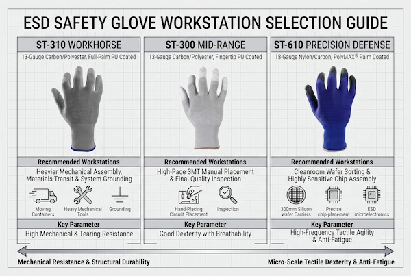
In front-end and semiconductor packaging and testing (OSAT) processes—such as wafer dicing, sorting, wire bonding, and advanced optical module assembly—equipment configuration imposes extremely stringent requirements for electrostatic sensitivity and cleanliness:
Recommended Standard Equipment: ST-610 (18-pin high-density ultra-fine nylon core with proprietary PolyMAX® black conductive coating);
Micrometer-level tactile sensitivity and operational precision: When operating vacuum pens, precision wafer tweezers, or directly handling bare chip frames, the ST-610’s 18-needle ultra-fine weave system eliminates excess fabric gaps on the inner side of the fingertips, providing a second-skin-like fit; Micromechanoreceptors can keenly detect minute changes in gripping force, effectively preventing wafer edge chipping or microcracks caused by gloves that are too thick and result in dull tactile feedback;
Ultra-dense micro-mesh eliminates the risk of Charge-Dissipating Model (CDM) failure: Bare chips handled at these workstations have gate oxide layers only a few nanometers thick, making them extremely sensitive to rapid transient discharges at extremely low voltages; The ST-610’s ultra-dense conductive micro-mesh, with a pitch of less than 2.5 millimeters, enables nanosecond-level equipotential balancing at any microscopic contact point on the glove’s surface, eliminating localized charge islands and completely preventing CDM hard breakdown triggered by electric field induction at the fingertips;
Class 100 Cleanliness and Zero Ion Contamination Control: The PolyMAX® conductive coating features outstanding physical cross-linking strength and abrasion resistance. Combined with a continuous nylon filament liner, it prevents the shedding of loose fibers or polymer debris during frequent handling of wafer carriers. The product undergoes ultrapure water cleaning to remove dust, and its particle shedding metrics consistently meet the ISO 14644-1 Class 5 cleanroom standard, preventing particulate matter from adhering to photolithography surfaces and causing widespread wafer scrap.
H3: High-Density SMT Component Placement and In-Line Inspection
In the mid-stage of surface-mount technology (SMT)—including high-speed component placement and feeding, manual insertion of irregularly shaped components, visual inspection (before and after AOI), and crimping of micro-flexible printed circuit boards (FPCs)—work operations are characterized by high cycle rates, prolonged continuous operation, and heavy strain on the fingertips:
Recommended Standard Equipment: ST-300 (13-pin carbon fiber composite polyester liner with microporous PU coating on fingertips);
Precise fingertip control and anti-slip protection: The ST-300 features microporous PU coating exclusively on the fingertips and pad areas; the microporous structure provides an excellent coefficient of static friction when contacting smooth reel spools, tape-and-reel covers, and plastic component casings, ensuring precise, slip-free pickup of tiny components while preventing human fingerprint oils from penetrating the pin surfaces;
Breathable, sweat-wicking ergonomics for the bare fabric palm: For microscope inspectors and re-stocking operators working continuously for hours, the skin on their hands is highly prone to heat buildup and sweating; The ST-300 fully retains the open micropores of the 13-gauge knit fabric in both the palm and back-of-hand areas, allowing air to freely circulate under the natural airflow at the workstation and rapidly evaporate sweat; this not only significantly enhances comfort during prolonged wear and reduces worker resistance but also prevents chemical corrosion and abnormal longitudinal resistance shifts caused by salt supersaturation from sweat inside the glove;
Localized, controlled discharge balances operational agility: The conductive coating on the fingertips seamlessly integrates with the carbon fiber network on the fingers, enabling controlled charge transfer within milliseconds of picking up a component. This balances the anti-static safety required for high-density assembly lines with the flexibility needed for high-cycle assembly operations.
H3: Chassis Assembly, Power Module Testing, and Box Build
In downstream processes such as complete unit enclosure assembly (Box Build), industrial control cabinet cable routing, server rack installation, pilot testing of power modules, and high-volume material handling, gloves must withstand intense mechanical stress and provide extensive current dissipation protection:
Recommended Standard Equipment: ST-310 (13-pin carbon fiber composite polyester liner with full-palm microporous conductive PU coating);
Full-palm dip-coating creates a large-area closed-loop grounding path: At these workstations, workers often need to support metal enclosures with their entire hands, handle black carbon-filled anti-static tote boxes, or secure large connectors; The ST-310’s full-foot conductive PU coating instantly creates a large-area grounding contact interface spanning hundreds of square centimeters when force is applied with both hands; this high-flux pathway smoothly diverts high-density charges from the equipment housing and the wearer’s body to grounded anti-static mats or metal assembly line tracks the moment contact is made, eliminating overcharging caused by excessive impedance at localized contact points;
Physical armor against scratches from metal burrs and sharp edges: Stamped cold-rolled steel enclosures, un-deburred aluminum extrusion frames, and the thick fiberglass edges of PCB panel assemblies can easily cause penetrating cuts to ordinary gloves; The ST-310 features a 13-strand twisted polyester filament liner combined with a full-palm thickened rubber coating, creating a highly durable physical abrasion-resistant layer. While withstanding continuous scraping, it firmly protects the embedded two-component carbon filaments from being pulled apart by external forces, maintaining stable mechanical toughness and electrostatic dissipation performance throughout the product’s entire lifecycle.
H2 (8): Technical FAQ: Yarn Physics and Knitted Liner Engineering
In the practical procurement and technical evaluation of anti-static equipment for microelectronics manufacturing and cleanrooms, engineering and technical personnel often encounter numerous questions regarding knitting specifications, knitting geometry, and material properties. The following provides an engineering analysis of the four most critical underlying technical issues of concern to production lines.
H3: FAQ 1: Does a higher gauge (18G vs. 13G) always imply better antistatic protection?
This is not necessarily the case. In textile engineering, “gauge” strictly refers to the number of knitting needles arranged per inch on the needle bed. It determines the fabric’s knitting density, thinness, and the denier of the fibers used, but it is not inherently equivalent to a glove’s electrostatic defense capability:
The decisive foundation of antistatic performance: A glove’s charge dissipation performance depends entirely on whether an intrinsic, continuous conductive network—exceeding the creep threshold—was established per unit area during the inner lining weaving process. If an 18-gauge glove uses only ordinary nylon blends with a minimal amount of discontinuous carbon fibers, or relies solely on surface chemical treatment, its electrostatic dissipation performance will be far inferior to that of a 13-gauge glove woven with scientifically proportioned continuous bicomponent conductive filaments;
Advantages of high-gauge knitting in charge capture rates: Assuming the use of the same high-quality continuous conductive carbon filaments, the 18-gauge process—due to its finer yarns and extremely dense knit structure—achieves a density of geometric contact junctions formed by the interwoven conductive fibers per unit area that is more than 60% higher than that of the 13-gauge process. The denser mesh nodes reduce the spacing between stripes to within 2.5 millimeters, significantly shortening the physical distance that charges must travel laterally across the insulating interface. Consequently, in terms of dynamic charge capture and potential equalization rates at the microsecond level, the high-gauge micro-mesh structure indeed demonstrates superior electrical response.
H3: FAQ 2: Why do bare-stripe ESD gloves fail during multi-axis stretching at the fingertips?
Many low-cost gloves are woven with unidirectional parallel carbon stripes spaced 10 mm or even 15 mm apart. While their impedance often meets standards during flat, static testing, their antistatic functionality rapidly fails once the gloves are worn and multi-axial stretching occurs at the fingertips:
The physics of geometric disconnection under radial stretching: When an operator bends their fingers or grips a workpiece firmly with their fingertips, the fabric at the fingertips of the gloves undergoes intense bidirectional or even multi-axial mechanical expansion and stretching. When subjected to lateral stretching, the polyester insulating gaps between the parallel stripes in the weave are forcibly widened several times over;
Blockage of lateral charge migration paths: Along the direction perpendicular to the stripes, the spatial span between fibers is significantly increased, causing the area of the already non-conductive insulating bands to expand dramatically. According to the slow relaxation laws of electrostatic charges at insulating interfaces, discrete charges generated by friction cannot cross the widened insulating gaps caused by stretching; instead, they become trapped within localized insulating regions, forming localized high-voltage micro-insulating islands that can trigger hard discharge breakdown upon contact with sensitive components;
Tensile Redundancy of Bidirectional Isotropic Grids: Compared to unidirectional stripes, gloves designed with a warp-and-weft interwoven isotropic microgrid (Grid Pattern) feature conductive fibers that form closed-loop interlocking structures in three-dimensional space; even when the fingertips undergo localized physical tensile deformation exceeding 30%, the grid undergoes only microscopic deformation without interrupting connectivity, and each microporous edge remains surrounded by conductive pathways, ensuring that charges can still be smoothly dissipated within a few milliseconds during dynamic pinching motions.
H3: FAQ 3: How does filament spinning prevent cleanroom contamination compared to spun yarn?
In semiconductor packaging and testing facilities and optical cleanrooms meeting ISO 14644-1 Class 5 (Class 100) standards or higher, the use of antistatic gloves made from any spun yarn is strictly prohibited; only continuous filament gloves are permitted:
The physical mechanism behind high dust generation in spun yarn: Spun yarn consists of thousands of short fibers (such as cotton staple fibers or chopped polyester fibers), each only tens of millimeters long, mechanically twisted and bound together into a cord; in this loose physical structure, a large number of fiber ends are inevitably exposed on the yarn’s surface, forming microscopic “fuzz” visible to the naked eye; When subjected to continuous material handling, finger manipulation, and airflow erosion on the production line, the short fibers—under the influence of shear stress—are highly prone to slipping out of and breaking away from the yarn body, thereby releasing large quantities of airborne particulate matter larger than 0.5 micrometers into the cleanroom air;
H3: FAQ 4: Can the ST-610 with PolyMAX® coating withstand live testing at 48V telecom stations?
Absolutely, and it offers an extremely high margin of intrinsic safety in terms of electrical safety:
Physical current clamping by dissipative materials: In live testing scenarios involving telecom base station power modules, hot-swapping of server racks, and 48V DC power busbars, the equipment must prevent electric shock to workers and eliminate discharge sparks. The ST-610 gloves, featuring the PolyMAX® black conductive coating, maintain a stable and controlled overall vertical penetration resistance within the anti-static dissipative range of 1.0 x 10^6 to 1.0 x 10^7 ohms;
Based on Ohm’s Law calculations for microampere-level leakage current: Assuming a worker wearing the gloves accidentally comes into contact with an exposed 48V DC copper busbar, calculations according to Ohm’s Law (current equals voltage divided by total resistance) show that even when using the lower limit of the glove’s dissipative impedance—1.0 × 10⁶ ohms (1 megohm)— the theoretical maximum leakage current flowing through the glove and into the human body at 48 V would be only 0.048 milliamps (i.e., 48 microamps);
This is far below the threshold for human perception and electric shock: The International Electrotechnical Commission (IEC) standard on the effects of power-frequency and direct current on the human body clearly states that the threshold for the human body to perceive a faint current is typically above 1 milliampere (1,000 microamperes), and the dangerous current level capable of causing muscle spasms is above 10 milliamperes; The extremely small current of 48 microamperes is only one-twentieth of the human perception threshold; it poses no risk of electric shock to the human nervous system or cardiac muscle tissue, nor does it generate a destructive micro-arc at the moment of electrical contact that could ablate the gold-plated contacts of the connector. This achieves a physical integration of microelectronic ESD dissipation and operator safety during low-voltage live-line work.
H2 (9): Enterprise QA Protocol: Verifying Yarn Integrity at Incoming QC (CTA)
When establishing a robust electrostatic defense barrier, the Quality Engineering (QE) team at the Microelectronics Assembly and Semiconductor Packaging and Testing (OSAT) facility must extend quality control measures all the way back to the incoming raw material inspection (IQC) stage. The vast majority of electrostatic incidents on production lines stem from companies placing undue trust in static single-test reports provided by suppliers, coupled with a lack of dynamic testing methods to evaluate fabrics under actual stress conditions. Only by establishing physical sampling criteria that account for microscopic deformation can the influx of substandard blended-fiber and chemically-treated gloves into the production floor be prevented before bulk materials enter production.
H3: Non-Destructive Incoming Verification: The 30% Dynamic Stretch Test
To quickly identify substandard anti-static gloves that are prone to tearing under mechanical bending, companies must abandon static readings taken from gloves laid flat in a relaxed state during incoming inspection and fully implement dynamic physical testing protocols that simulate the tension of a hand grip:
Rigorous Pre-Treatment in a Low-Humidity Environment (25% RH Humidity Conditioning): In accordance with internationally recognized sampling standards, a sufficient number of glove samples must be randomly selected from the incoming batch; prior to testing, samples must be laid flat in a controlled constant-temperature and constant-humidity test chamber and left to equilibrate in a dry environment at 23 degrees Celsius and 25% relative humidity for at least 24 hours; The core of this step is to forcibly evaporate the air-water film adsorbed on the glove’s surface, thoroughly eliminating the false compensation of environmental moisture on the fabric’s electrical resistance and forcing the material to exhibit its true intrinsic conductivity;
Apply a 30% linear mechanical tensile strain: Mount the moisture-conditioned glove samples on a specialized bidirectional mechanical tensile insulation fixture, and apply a precise 30% linear mechanical tensile strain along both the warp and weft directions to the palm area of the glove as well as the knuckles of the index and middle fingers—which bear the greatest stress; This strain magnitude precisely replicates the maximum geometric expansion limit that the glove’s fiber mesh undergoes when workers grasp tools and flex their fingers;
5-pound hammer probe dynamic impedance verification: While the glove is maintained at a 30% tensile strain, a 5-pound concentric double-ring hammer probe compliant with the ANSI/ESD STM11.11 standard is immediately and gently pressed onto the tensile stress zone, and a 100-volt DC test voltage is applied; The actual resistance reading from a high-precision high-resistance meter must remain stable and converge within the controlled dissipation range of 1.0 × 10⁶ to 1.0 × 10⁸ ohms; If the reading experiences a significant jump or even surges beyond 1.0 × 10⁹ ohms at the moment of tension application, this indicates that microscopic dislocations have caused an open circuit in the internal conductive filaments under tensile stress, or that the gaps between the mesh have expanded excessively. All materials in this batch must be deemed nonconforming and returned.
H3: Deploying Enterprise ESD Knitted Assets Directly from the Manufacturer
Multinational electronic manufacturing services (EMS) giants and wafer processing companies are accelerating the elimination of multi-tiered intermediaries lacking technical verification capabilities when managing their consumables supply chains. Instead, they are shifting entirely toward technical collaboration with source manufacturing plants that possess full vertical integration capabilities—from spinning and weaving to coating:
End-to-End Batch Traceability and Raw Material COA Assurance: Direct collaboration with physical manufacturing facilities enables buyers to look beyond the finished casing and directly access the nano-carbon black doping purity, scanning electron microscope (SEM) images of the filament cross-section, and the Certificate of Analysis (COA) for each batch of conductive composite filaments; Source manufacturers can provide raw test curves for tensile strength, wash resistance, and particle leaching (LPC) for each production batch number, eliminating batch mixing and the substitution of inferior products during the distribution process;
Support for Customized Geometric Weaving and Ergonomic Validation: The source manufacturing system can collaborate with the customer’s ESD committee to tailor the blend ratio of 13-gauge and 18-gauge yarns and the coating formulations on demand, based on specific production line requirements for wear resistance, ultra-agility, or ultra-low dust emission, providing in-depth technical solution support;
Request Original Manufacturer Engineering-Grade Evaluation Materials: To assist your engineering team in verifying the physical dissipation performance of 13-gauge medium-weight polyester liners and 18-gauge ultra-fine nylon micro-mesh under actual production line conditions, we have opened an exclusive engineering testing channel for high-reliability manufacturing enterprises worldwide. You can contact our technical support team immediately: Request Enterprise ESD Yarn Sample Swatches & Evaluation Kit.


